Table of Contents
Advertisement
Quick Links
Sony Corporation
MVS-6500 System
(SY)
4-448-461-11 (1)
Printed on recycled paper.
Multi Format Switcher System
MVS-6500 System
(With ICP-6520/6530 Control Panel)
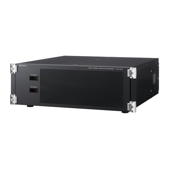
MVS-6520
ICP-6511
Startup Guide
Software Version 1.00 and Later
Printed in Japan
2012.09 32
1st Edition
© 2012
MVS-6530
ICP-6520
MKS-6550
MKS-6570
[English]
ICP-6530
Advertisement
Table of Contents

Related Manuals for Sony MVS-6500 System


Summary of Contents for Sony MVS-6500 System
- Page 1 Multi Format Switcher System MVS-6500 System (With ICP-6520/6530 Control Panel) MVS-6520 MVS-6530 ICP-6520 ICP-6530 ICP-6511 MKS-6550 MKS-6570 Startup Guide [English] Sony Corporation Software Version 1.00 and Later MVS-6500 System Printed in Japan (SY) 2012.09 32 1st Edition 4-448-461-11 (1) © 2012...
- Page 2 NOTICE TO USERS © 2012 Sony Corporation. All rights reserved. This manual or the software described herein, in whole or in part, may not be reproduced, translated or reduced to any machine readable form without prior written approval from Sony Corporation.
-
Page 3: Table Of Contents
Setting Up a Removable Disk for Use ..39 Saving/Recalling User Settings on Removable Connection Disks ..........39 MVS-6500 System Configuration..... 10 Setting Simple Connection of AUX Bus Remote Panel ........41 Video Input/Output Systems....... 10 Device Control Systems......11 Connecting Devices........ -
Page 4: Overview
Overview Introduction The Startup Guide (this document) describes the basic settings and operations to begin using the MVS system. For details about settings and operations, refer to the User’s Guide. Introduction... -
Page 5: Names Of Parts
Names of Parts MVS-6520/6530 Multi Format Switcher Processor Rear panel: MVS-6520 Slots 1 to 5 a -AC IN A and B connectors Slots 6 to 8 b U terminal Slots 1 to 5 c PRIMARY INPUTS 1 to 32 connectors d OUTPUTS 1 to 16 connectors Slots 6 to 8 e TALLY/GPI IN 1 to 18 and TALLY/... - Page 6 Rear panel: MVS-6530 Slots 1 to 5 a -AC IN A and B connectors Slots 6 to 8 b U terminal Slots 1 to 5 c PRIMARY INPUTS 1 to 48 connectors d OUTPUTS 1 to 32 connectors Slots 6 to 8 e TALLY/GPI IN 1 to 18 and TALLY/ GPI OUT 1 to 48 connectors h UTIL (FM) connector...
- Page 7 There is a risk of damage to the BNC-type connectors and cable. i FM (frame memory) DEVICE connector (USB 2.0 2) For information about devices that can be connected, contact your Sony compliant) representative.
-
Page 8: Icp-6520/6530 Control Panel
AC power cords. The unit is equipped with two power supplies. When A or B power supply is connected, unit operation can proceed. 1) For information about devices that can be connected, contact your Sony representative. Names of Parts... -
Page 9: Icp-6511 Menu Panel
ICP-6511 Menu Panel The menu panel is optional. Bottom panel DVI-D DEVICE c DC IN connector b DVI-D connector a DEVICE connector a DEVICE connector (USB 2.0, USB Type-B) Side panel Connect to the DEVICE 1 connector of the ICP-6520/ 6530. -
Page 10: Connection
Connection MVS-6500 System Configuration Video Input/Output Systems EJECT Character generator ACCESS NETWORK MARK1 MENU CHAPTER LOCAL REMOTE THUMB EXPAND RESET CLIP NAIL LEVEL PAGE DISPLAY CLIP ESSENCE MENU MARK MARK2 PREV PLAY NEXT STOP SHUTTLE PHONES CH 1 CH 2... -
Page 11: Device Control Systems
KEY INHI VARIABLE PRESET (RS-422A) SHIFT F REV F FWD STANDBY VTRs and DDRs Control devices connected using Sony 9-pin VTR, VDCP, or P-Bus protocols (RS-422A) Removable REMOTE 1 to 4 REMOTE S1 and S2 disk ICP-6511 Menu Panel MVS-6520/6530... -
Page 12: Connecting Devices
Connecting Devices This section describes the connection procedure for the • ICP-6511 Menu Panel following system configuration as an example. • Cameras for recording (4) • MVS-6520 Switcher Processor • VTRs for playback (2) (with MKS-6550 Format Converter Board and MKS- •... -
Page 13: Peripheral Device Connection
b Connect the DEVICE 1 connector of the control Connect the control panel and menu panel. panel and the DEVICE connector on the bottom of a Connect the DVI-D connector of the control panel the menu panel using the USB cable supplied with and the DVI-D connector of the menu panel using the menu panel. - Page 14 In this example, connect two monitors to connector of the control panel using a USB cable. OUTPUTS 1 and 2. For details about connecting monitors, contact your Sony b Connect the monitor for multi viewer. representative. In this example, connect to OUTPUTS 9.
-
Page 15: Preparation
Preparation Preparation Procedure This section describes the setup required before operation in the MVS system. Turn on the power (1 p. 16) System settings Configure the network (1 p. 19) Set the signal format (1 p. 20) Signal settings Assign input signals (1 p. 21) Assign output signals (1 p. -
Page 16: Turning Power On/Off
Turning Power On/Off After connecting the system, turn on the power using the following procedure. MVS-6520/6530 Switcher Processor ICP-6520 Control Panel ICP-6530 Control Panel Set the POWER A and B switches of the switcher processor to ON (“?” side). When the switcher processor is turned on, the status indicators for supplies A and B light green. - Page 17 While the system is accessing the local disk or frame memory external HDD, the indicator on the menu page number button lights red. Check to make sure the indicator is not lit before turning off the power. Indicator on the menu page number button (ICP-6520 control panel display.
-
Page 18: Opening Menus
A shutdown confirmation message appears. Memo Press [Yes] to commence shutdown. The process is You can also open the top menus using the top menu completed when the menu screen goes completely selection buttons in the menu panel. black. Check that the POWER switch indicator “1” on the control panel has gone out. -
Page 19: Configuring The Network
Configuring the Network Control panel Switcher processor When power is turned on, all devices connected to the MVS system LAN are detected and corresponding settings are registered. Display the menu. a Open the Engineering Setup >System >Network Config menu (7311). Register the list of detected devices. -
Page 20: Setting Signal Formats
Set the formats. Setting Signal Formats Setting the Signal Format You can set the signal format and the input reference signal format of each device that is automatically detected. The combinations of signal formats and input reference signals that can be configured are as follows. Signal format System Signal format... -
Page 21: Setting The Screen Aspect Ratio
b Check the message, then press [Yes]. Assigning Signals to A progress bar is displayed during the configuration. Cross-Point Buttons The system restarts when the configuration is completed. To select input signals using cross-point buttons, the Setting the Screen Aspect Ratio signals must be assigned to each of the cross-point buttons in advance. -
Page 22: Assigning Pair Signals To Cross-Point Buttons
Assign a video signal to the cross-point button. Enter Keyboard window Video d Press [Enter]. e Repeat steps 1 to 4 as required to assign other Main, V/K Pair Assign menu signals. a In the [V/K] column of the list on the left, select the number of the cross-point button. -
Page 23: Assigning Output Signals
Set a monitor for preview output. Assigning Output Signals a In the <Output Assign> group, select [Re-Entry Source]. b In the [Out#] column in the list on the left, select the You can set the signals output to the connected devices on number for the OUTPUTS connector connected to the OUTPUTS of the switcher processor. -
Page 24: Using Multi Viewer
Set the multi viewer outputs. Using Multi Viewer Out# Src# The screen of a monitor connected to the MVS system can be split to view multiple video signals simultaneously. The screen can be split into four or ten subscreens. Split into four Subscreen signals Output/MV/FC/DME Output Assign menu... -
Page 25: Assigning Signals To Subscreens
Set the display method of the screen. Assign an output signal to a subscreen. Win# Split Mode Multi Viewer Output Multi Viewer menu Source/Output Assign menu a In the <Multi Viewer> group, select the target multi viewer. a In the <Source/Output Select> group, select In this example, select [1]. -
Page 26: Setting Multi Viewer Tally Output
c In the list on the right, select the signal you want to Setting Tally assign. In this example, select “CAM1”. d Press [Set]. Setting Parallel Tally Repeat steps 2 and 3 as required to assign other signals to other subscreens. The red tallies for PRIMARY INPUTS 1 to 48 are assigned to the TALLY connector on the switcher processor by default. - Page 27 g In the Tally Enable menu (7364), check the tally Set the tally generation reference. settings for the preview output. If the settings of “OUT002” are as follows, you do not need to change the settings. Proceed to step 3. Destination Level Tally Type Enable Setting OUT002...
- Page 28 (7366) in step 3 and make settings. Primary 36 Primary 37 For details about settings, refer to the User’s Guide. Primary 38 Primary 39 Input/outputs for MVS-6500 system assigned to S-Bus matrix Primary 40 Primary 41 Matrix size: 136 x 138 Primary 42 Primary 43 •...
- Page 29 Source Source M/E-2 Out 3 M/E-2 Out 4 FC 1 FC 2 FC 3 FC 4 P/P Out 1 FC 5 P/P Out 2 FC 6 P/P Out 3 FC 7 P/P Out 4 FC 8 Black White Color Bkgd 1 Color Bkgd 2 DME 1 DME 2...
- Page 30 Destination Destination Out 10 Out 11 Out 12 M/E-1 Bkgd A Out 13 M/E-1 Bkgd B Out 14 M/E-1 Utility 1 Out 15 Out 16 M/E-1 Key 1 Fill Out 17 M/E-1 Key 1 Source Out 18 M/E-1 Key 2 Fill Out 19 M/E-1 Key 2 Source Out 20...
- Page 31 Matrix size: 128 x 128 Destination (Numbers in parentheses indicate the number for 136 x 138 matrix size.) P/P Bkgd A • Source P/P Bkgd B Source P/P Utility 1 Primary 1 Primary 2 P/P Key 1 Fill Primary 3 P/P Key 1 Source Primary 4 P/P Key 2 Fill...
- Page 32 Source Source Primary 41 Frame Memory 2 Primary 42 Frame Memory 3 Primary 43 Frame Memory 4 Primary 44 Frame Memory 5 Primary 45 Frame Memory 6 Primary 46 Frame Memory 7 Primary 47 Frame Memory 8 Primary 48 DME Monitor Video DME Monitor Key M/E-1 Out 1 M/E-1 Out 2...
- Page 33 • Destination (Bus) Destination Destination Out 1 Out 2 Out 3 Out 4 Out 5 Out 6 Out 7 Out 8 Out 9 Out 10 Out 11 M/E-1 Bkgd A Out 12 M/E-1 Bkgd B Out 13 M/E-1 Utility 1 Out 14 Out 15 M/E-1 Key 1 Fill...
- Page 34 Destination Bit No. Source P/P Key 7 Source (96) Primary 2 P/P Key 8 Fill (97) Primary 3 P/P Key 8 Source (98) Primary 4 P/P Bkgd A (102) Primary 5 P/P Bkgd B (103) Primary 6 P/P Utility 1 (104) Primary 7 Primary 8 P/P Key 1 Fill (106)
- Page 35 Bit No. Source Bit No. Source Primary 47 Frame Memory 8 Primary 48 DME Monitor Video DME Monitor Key M/E-1 Out 1 M/E-1 Out 2 M/E-1 Out 3 M/E-1 Out 4 M/E-2 Out 1 M/E-2 Out 2 M/E-2 Out 3 M/E-2 Out 4 P/P Out 1 P/P Out 2...
-
Page 36: Assigning 8-Keyer Buttons
b In the list on the right, select the key to assign. Assigning 8-Keyer In this example, select [KEY5]. c Press [Set]. Buttons d Repeat steps a to c to assign [KEY6] to [KEY8] to button numbers “6” to “8”, respectively. In the MVS-6530 (3M/E processor), eight keyers can be Assigning Key Selection Functions used in the PGM/PST banks. -
Page 37: Setting The Startup State
Assign the [SHIFT] and [ADD] functions to buttons. Setting the Startup State a In the button diagram on the left, select the target button. In this example, select a blank button. b In the list on the right, select [SHIFT]. Selecting the Startup Mode at Power c Press [Set]. -
Page 38: Customizing The User Default Settings
power is applied, see “Customizing the User You can customize and save user default settings to recall Default Settings” (1 p. 38). the same operation state when power is turned on. Or you can recall saved user settings to return to a known state if Factory default settings an error occurs. -
Page 39: Saving Data To Removable Disk
Displaying the removable disk information. Saving Data to Total data capacity Removable Disk Used capacity Mount Point Free capacity Setting Up a Removable Disk for Use To use USB flash memory or other removable disk with the MVS system, you must register it as a primary device beforehand. - Page 40 This section describes the procedure for operations for the Execute a save or recall operation. “Setup” data file. To save data a Press [t Save]. Memo To recall data You can save register data containing snapshots, a In the [Removable Disk] list on the right, select the keyframes, macros and other data on a removable disk and file you want to recall.
-
Page 41: Setting Simple Connection Of Aux Bus Remote Panel
For information about the input signals and buses that can b Select the control panel “PNL1” in the [Device] be controlled by the MKS-8080/8082, see “Input/outputs column. for MVS-6500 system assigned to S-Bus matrix” c In the <Initialize> group, select [Reset]. (1 p. 28). d Press [Execute]. - Page 42 c In the <Matrix Size> group, select the matrix size. In this example, select [136x138 (Standard)]. d Set each of the [Source], [Destination], and [Level] parameters to “1”. Notes After changing the settings, save the user default settings as required. For details about saving data, see “Setting the Startup State”...
-
Page 43: Basic Image Creation Operations
Basic Image Creation Operations Video Switching (Transitions) Types of Transitions (Mix/NAM/Wipe/DME Wipe) A separate video progressively fades in over the current video. The whole of the source video gradually fades out while the new video gradually fades in. The output comprises 50% of each video when the fader lever is in the center position. Background A 50% A and 50% B output Background B... -
Page 44: Names Of Parts In The Control Panel
DME wipe The video changes in a DME wipe pattern that uses image shrinking/magnification or other DME effects. Background A Background B Names of Parts in the Control Panel The positions of the principal parts and fader lever used in the following description are shown in the following figure. 2nd row 1st row Cross-point control block... -
Page 45: Video Transitions Using Wipes Or Mixes
The transition is executed, interchanging the cross- points in the background A and B rows. Background A row Background A video before the transition Select the video you want to display after the Lit buttons are Background B row interchanged transition. - Page 46 Select the portion of the image to change using the transition. Press one of the next transition selection buttons in the transition control block, turning it on. • [BKGD] button: Changes the background. • [KEY1] to [KEY4] buttons: Inserts (or deletes) key 1 to key 4, respectively.
- Page 47 Transition rate display AUTO TRANS button Fader lever Transition control block The output comprises 50% each of both background A and background B video when the fader lever is in the center position. Background A Background B Mid transition state Memo When you press the [AUTO TRANS] button, the transition is executed automatically according to the...
-
Page 48: Saving Dme Wipe Settings In A Dme Wipe Snapshot
Saving DME Wipe Settings in a DME Wipe Snapshot Notes The optional DME board (MKS-6570) is required for DME wipes. Setting Picture-in-Picture (DME Wipe) Apply a border to the picture-in-picture pattern. (The Set the size of the DME wipe pattern. following describes the M/E bank, as an example.) a Open the M/E-1 >DME Wipe >Modify menu (1165). -
Page 49: Saving/Recalling A Dme Wipe Snapshot
Position Width Border Luminance Modify menu Saturation b Adjust the [H] parameter to set the horizontal position. Edge/Direction menu c Adjust the [V] parameter to set the vertical position. b In the <Edge> group , press [Border], turning it on. c Adjust the [Width] parameter to set the width of the border. - Page 50 Register the DME wipe snapshot in a button. a In the Flexi Pad, press the [DME WIPE] button. b Press the [M/E1] button. c Holding down the [DME WIPE] button, press the button you want to register (0 to 9). The button lights yellow when successfully registered.
-
Page 51: Inserting Titles (Keys)
Inserting Titles (Keys) What is a Key? On the switcher, you can overlay video containing a title or A key is comprised by a signal that describes how the other material occupying part of the screen (key) over the background is cut out (key source) and the video signal the video displayed on the whole screen (background). - Page 52 KEY ADJ button KEY1 button Insert keys 2 to 4. a Press the [KEY2] button, turning it on. b Repeat steps 3 and 4 to insert key 2. c Set key 3 and key 4, as required. M/E1 button KEY2 button AUTO SEL button LUM button Flexi Pad...
- Page 53 KEY1 button Key priority display PRIOR SET button KEY PRIOR button Transition control block Key 1 and key 2 priority changed Inserting Titles (Keys)
-
Page 54: Composing Images Using Chroma Keys
Composing Images using Chroma Keys Combine images of people and scenery using keys. (The KEY ADJ button following describes key 1 on the M/E bank, as an KEY1 button example.) Select the key video. a In the 1st row of the cross-point control block, press the [KEY1] button, turning it on. - Page 55 Memo It is possible to move and magnify/shrink the key using a resizer or DME. Composing Images using Chroma Keys...
- Page 56 Composing Images using Chroma Keys...
- Page 57 The material contained in this manual consists of information Trademarks that is the property of Sony Corporation and is intended solely The products or system names appearing in this document for use by the purchasers of the equipment described in this are trademarks or registered trademarks of their respective manual.
Need help?
Do you have a question about the MVS-6500 System and is the answer not in the manual?
Questions and answers