Webasto Air Top 2000 STC Installation Instructions Manual
Hide thumbs
Also See for Air Top 2000 STC:
- Workshop manual (74 pages) ,
- Installation manual (41 pages)
Table of Contents

Related Manuals for Webasto Air Top 2000 STC


Summary of Contents for Webasto Air Top 2000 STC
- Page 1 Luftheizgeräte Einbauanweisung Air Heaters Installation Instructions Luchtverwarmingsapparaten Montagehandleiding Air Top 2000 STC Handelsbezeichnungen/Trade names/Handelsnamen: Air Top 2000 STC B (Benzin/petrol/benzine) Air Top 2000 STC D (Diesel/FAME)
- Page 2 Only genuine Webasto parts may be used. See also Webasto air and water heaters accessories catalogue. NEVER try to install or repair Webasto heating or cooling systems if you have not completed a Webasto training course, you do not have the necessary technical skills and you do not have the technical documentation, tools and equipment available to ensure that you can complete the installation and repair work properly.
-
Page 3: Table Of Contents
Air Top 2000 STC Inhaltsverzeichnis Table of Contents Gesetzliche Bestimmungen für den Einbau ... . . 1 Statutory regulations governing installation ...41 Verwendung der Luftheizgeräte . -
Page 4: Statutory Regulations Governing Installation
Statutory regulations governing installation Statutory regulations governing installation The Air Top 2000 STC heater has been type-tested and approved in accord- • The electrical cable/wiring harness must be sufficiently dimensioned to pre- ance with ECE-R 10 (EMC) and ECE-R 122 (heater). - Page 5 Statutory regulations governing installation Air Top 2000 STC Requirements relating to the basic unit: 5.3.2.4 The label referred to in Annex 7, paragraph 4, or a duplicate, must be positioned so that it can be easily read when the combustion heater is When switched off, it is permissible for combustion heaters to continue installed in the vehicle.
- Page 6 Air Top 2000 STC Statutory regulations governing installation 5.3.6.2 The inlet duct must be protected by mesh or other suitable means. The installation of the heater in a place that is inaccessible while driving or 5.3.7 Heating air outlet in a suitable enclosure conforming to Paragraphs 5.3.2.2 and 5.3.2.5 is 5.3.7.1 Any ducting used to route the hot air through the vehicle must be...
- Page 7 Statutory regulations governing installation Air Top 2000 STC 3.1.2 The combustion heater shall be switched on manually. Programming devices shall be prohibited. 3.2 EX/II, EX/III and MEMU vehicles Combustion heaters using gaseous fuels are not permitted. 3.3 FL vehicles 3.3.1 The combustion heaters shall be put out of operation by at least the following methods: Intentional manual switching off from the driver’s cab;...
-
Page 8: Use Of Air Heaters
Air Top 2000 STC Use of air heaters Use of air heaters The Webasto Air Top 2000 STC air heaters are designed – to heat cabins, boats, commercial vehicles, minibusses, vans/transporters and motor homes – to defrost vehicle windows. The heaters operate independently of the engine and are connected directly to the fuel tank and the electrical system of the vehicle. -
Page 9: Installation
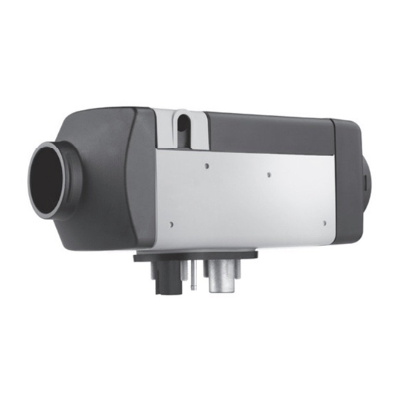
Comply with the legal requirements for installation on Page 41 and 42. The When installing the Air Top 2000 STC heater, tighten the M6 nuts to a torque requirements stipulated in the latest version of the ADR must be additionally of 6 Nm +1. - Page 10 Air Top 2000 STC Installation Cold air inlet Cable outlet (optionally on right or left) Hot air outlet Exhaust gas outlet Fuel inlet Combustion air inlet Space requirements for hot air outlet Space requirements for cold air inlet Space requirements for removing heater >155...
- Page 11 Installation Air Top 2000 STC Diesel: Fig. 3: Seal Ensure ease of movement of Petrol: horizontal all moving parts! Fig. 2: Permissible heater installation positions Fig. 4: Installation...
-
Page 12: Type Label
Air Top 2000 STC Type label Type label If the type label is not visible with the heater in installed position, a duplicate of the type plate must be displayed in a position where it is clearly visible and protected from damage. -
Page 13: Installation Example
Installation example Air Top 2000 STC Installation example Control element Heater Fuse Tank extracting device Fuel filter (accessory) Fuel pump Exhaust silencer (accessory) Combustion air intake line Combustion air intake silencer (accessory) ... -
Page 14: Hot Air System
Air Top 2000 STC Hot air system Hot air system NOTE: ATTENTION: it is not permitted to integrate the heater into the vehicle's air circulation Every reasonable precaution should be taken in positioning the heater to system. minimize the risk of injury and damage to personal property. - Page 15 Hot air system Air Top 2000 STC ATTENTION: 6.1. Room temperature sensor Suitable grilles must be fitted on the cold air inlet and hot air outlet if the For fresh air mode, a room temperature sensor must be installed in the area heater is used without air guides.
-
Page 16: Fuel Supply
Fig. 10). Separate fuel extraction has no influence on the pressure. from the return line using the Webasto fuel extractor (Fig. 8). In this case it is necessary to ensure that the return line extends almost to the bottom of the fuel tank (otherwise the Webasto tank extracting device (Fig. - Page 17 Fuel supply Air Top 2000 STC Seal Hole pattern Tank extracting device Use tank extracting device only with metal fuel tanks Tank fitting Minimum distance 25 mm Fig. 9: Webasto tank extracting device Plastic fuel tank Fig. 11: Extracting fuel from plastic fuel tank...
- Page 18 Air Top 2000 STC Fuel supply 7.1.4. Pipe lengths and delivery head When installing the fuel line make sure that it is kept as short as possible. See Fig. 12. The pipe must be installed such as to protect it from being damaged.
- Page 19 Fuel supply Air Top 2000 STC The fuel lines must be secured using state-of-the-art fastening elements. Parameter Value Do not damage the fuel line. Length of intake pipe l max. 5 Length of pressure pipe l max. 10 Intake side:...
- Page 20 The fuel pump is a combined delivery, metering and a shut-off system and is Due to the risk of corrosion only genuine Webasto parts must be used for subject to certain installation criteria (see Fig. 14).
-
Page 21: Combustion Air Supply
Using a combustion air line, the combustion air must be taken from a position that is as cool as possible and protected from splash water. Only use the supplied and Webasto-approved combustion air lines for this purpose. The combustion air opening must not be below the fording height permitted for the respective vehicle. -
Page 22: Exhaust Pipe
Air Top 2000 STC Exhaust pipe Exhaust pipe Rigid pipes made from unalloyed or alloyed steel with a minimum wall thickness of 1.0 mm or flexible piping made of alloyed steel must be used for the exhaust pipe. The exhaust pipe is secured to the heater with the supplied exhaust pipe clamp. -
Page 23: Combustion Air Intake And Exhaust Pipes
Combustion air intake and exhaust pipes Air Top 2000 STC Combustion air intake and exhaust pipes Both pipes must be installed falling away from the heater. If this is not possible, make a ø 4 mm condensation drain hole at the lowest point. - Page 24 Air Top 2000 STC Combustion air intake and exhaust pipes Attachment no further than 150 mm from the end of the exhaust pipe is required to achieve the required angle of 90° ±10°. Outflow direction almost vertical 90° ±10° Fig. 21: End of exhaust pipe...
-
Page 25: Electrical Connections
Electrical Connections Air Top 2000 STC Electrical Connections All lines that are not required must be insulated! 11.1. Connection for installation in a vehicle for transporting dangerous goods (ADR) The requirements stipulated in the ADR/RID Part 9, 9.2.4.7 Combustion Heaters must be additionally observed for the installation of the Air Top 2000 STC D heaters in vehicles used to transport dangerous goods. - Page 26 Air Top 2000 STC Electrical Connections An additional blade terminal fuse holder is to be installed to protect the F = 15A heater (supplied with the heater). The fuse holder must only be installed in (12 and 24V) the vehicle interior.
- Page 27 Electrical Connections Air Top 2000 STC 11.4. Control element connection The wiring harness is prepared for connection to the control element. Only pull on the connector housing to unplug the connector. The connector housing will lock (self-locking action) by pulling on the wiring harness.
-
Page 28: Connection Diagram/Wiring Diagram
Air Top 2000 STC Connection diagram/wiring diagram Connection diagram/wiring diagram 9032412A02 Fig. 28: System wiring diagram Air Top 2000 STC, 12 V/24 V with MultiControl, see Page 70 for legend... - Page 29 Connection diagram/wiring diagram Air Top 2000 STC 9032487A01 Fig. 29: System wiring diagram Air Top 2000 STC, 12 V/24 V with control element and vehicle fan, see Page 70 for legend...
- Page 30 Air Top 2000 STC Connection diagram/wiring diagram 9032490A01 Fig. 30: System wiring diagram Air Top 2000 STC, 12 V/24 V with standard timer/combination timer, see Page 70 for legend...
- Page 31 Connection diagram/wiring diagram Air Top 2000 STC 9032489A01 Fig. 31: System wiring diagram Air Top 2000 STC D, 12 V/24 V ADR-operation with SmartControl, see Page 70 for legend...
- Page 32 Air Top 2000 STC Connection diagram/wiring diagram 9032488A01 Fig. 32: System wiring diagram Air Top 2000 STC, 12 V/24 V ADR-operation with control element, see Page 70 for legend...
-
Page 33: Legend To Wiring Diagrams
Legend to wiring diagrams Air Top 2000 STC Legend to wiring diagrams Item Description Remarks Cable cross-sections Heater Air Top 2000 STC < 7.5 m 7.5 - 15 m Control unit Control unit UniBox 0.75 mm 1.0 mm Flame monitor Only for petrol heaters 1.0 mm... - Page 34 Air Top 2000 STC Legend to wiring diagrams Item Description Remarks Item Description Remarks Bulb/LED (in Item P) Display and button lighting V1-V2 Blocking diode Min. 500 mA Bulb/LED ON indicator, pumping device X1-X6 Plug connection To Item A2 (max. 500 mA)
- Page 35 Auxiliary drive All heater versions: connection W-bus diagnosis, SmartControl/ MultiControl, ThermoCall or Telestart (12V only). Terminal D+ W-bus (Webasto Thermo Test Diagnosis connection) CO2 setting (see workshop manual) K-bus Connection to terminal 30: Continuous heating mode is possible ...
-
Page 36: Initial Start-Up
Air Top 2000 STC Initial start-up Initial start-up Carefully bleed the fuel supply system after installing the heater. NOTE: Due to the low fuel consumption, it is necessary to switch on the heater several times to fill the fuel line. -
Page 37: Fault Switch-Off
Fault switch-off Air Top 2000 STC Fault switch-off The control unit identifies faults in individual heater components and mal- Rectify fault. functions during operation. Briefly switch the heater on and off (at least 2 seconds) to reset fault lock- out. - Page 38 Air Top 2000 STC Fault switch-off 15.1. Fault code output NOTE: After a fault has occurred in heaters with a control element, the fault code is output by the switch-on indicator/fault code indicator lamp flashing. After 5 fast flash pulses, the fault code is output by a sequence of long flash pulses, corresponding to the numbers in the table below.
-
Page 39: Technical Data
15 minutes to fill the fuel system with the new fuel. 16.2. Fuel for Air Top 2000 STC B (petrol): The Air Top 2000 STC D heaters are also approved for use with biodiesel The fuel specified by the vehicle manufacturer must be used. - Page 40 Air Top 2000 STC Technical data Heater Operation Air Top 2000 STC B Air Top 2000 STC D Type approval E1 R10- 04 1085 Heater E1 R122- 00 0216 Design Air heater with evaporator burner Heat flow Control range 1.0 - 2.0 kW 0.9 - 2.0 kW...
-
Page 41: Variants
Variants Air Top 2000 STC Variants Air Top 2000 STC B (petrol) Air heater for petrol (12 V) Air Top 2000 STC D (Diesel) Air heater for diesel/fuel oil EL (12 or 24 V) -
Page 42: Drilling Template
Air Top 2000 STC Drilling template Drilling template Seal NOTE: Max. base unevenness in area of seal: 1 mm Fig. 33: Drilling template... - Page 43 In multilingual versions the German language is binding. The telephone number of each country can be found in the Webasto service center leaflet or the website of the respective Webasto representative of your country. En cas de version multilingue, c’est la langue allemande qui fait foi.
Need help?
Do you have a question about the Air Top 2000 STC and is the answer not in the manual?
Questions and answers