Webasto Air Top 2000 STC Workshop Manual
Hide thumbs
Also See for Air Top 2000 STC:
- Installation instructions manual (43 pages) ,
- Installation manual (41 pages)

Related Manuals for Webasto Air Top 2000 STC


Summary of Contents for Webasto Air Top 2000 STC
- Page 1 Luft-Heizgeräte 03/2003 Air Heaters Workshop Manual Air Top 2000 STC Trade names: Air Top 2000 STC B (petrol) Air Top 2000 STC D (diesel)
- Page 2 Only genuine Webasto parts may be used. See also Webasto air and water heaters accessories catalogue. NEVER try to install or repair Webasto heating or cooling systems if you have not completed a Webasto training course, you do not have the necessary technical skills and you do not have the technical documentation, tools and equipment available to ensure that you can complete the installation and repair work properly.
-
Page 3: Table Of Contents
Fault code output (hexadecimal / Webasto Thermo Test) ....... . . - Page 4 Webasto tank extracting device for plastic fuel tank ......803 8.6.2.5 Webasto tank extracting device for metal tank ......803 8.6.2.6 Fuel lines .
- Page 5 Air Top 2000 STC Table of Contents Repair ................901 General information.
- Page 6 System wiring diagram Air Top 2000 STC, 12 V/24 V with rotary switch ......
-
Page 7: Introduction
Throughout this manual, the signal words CAUTION, ATTEN- old overheating sensor. TION and NOTE have the following meanings: The Air Top 2000 STC heaters are prepared for interior instal- CAUTION lation and and sealing directly on the driver's cab floor or This signal word is used to highlight operating instructions or wall. - Page 8 If this action does not produce the required success (if the heater overheats again), take it to a Webasto • The tanks must not be installed in the passenger's authorised workshop.
- Page 9 Air Top 2000 STC 1 Introduction Page for notes...
-
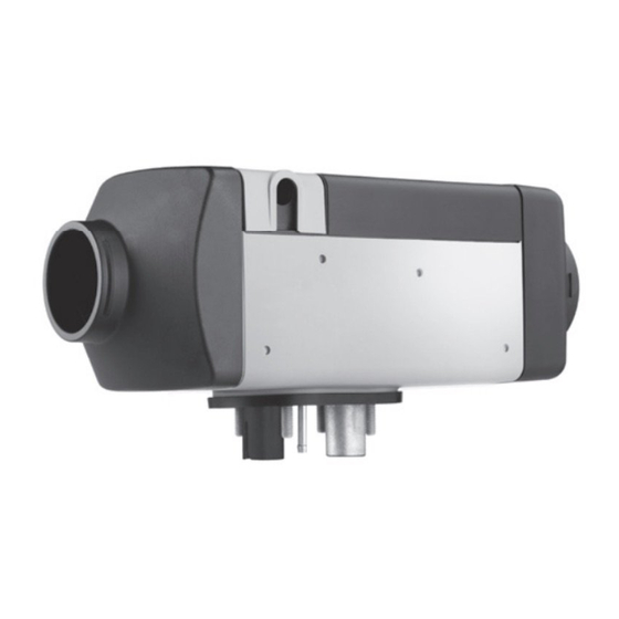
Page 10: Fig. 201 Air Heater Air Top 2000 Stc
2 General description Air Top 2000 STC General description The Air Top 2000 STC air heater is based on the evaporator principle and essentially consists of: – Drive unit (combustion air fan, heating air fan and drive motor) – Heat exchanger –... -
Page 11: Fig. 204 Heat Exchanger
Air Top 2000 STC 2 General description Heat exchanger Control unit In the heat exchanger, the heat generated by the combustion The control unit is the central component for ensuring process is transferred to the air delivered by the heating air trouble-free operation. -
Page 12: Fig. 208 Glow Plug
2 General description Air Top 2000 STC Glow plug Fuel pump The fuel/air mixture is ignited by the glow plug when the The fuel pump is a combined delivery, metering and a shut- heater is started. The glow plug is designed as an electrical off system for supplying fuel to the heater. - Page 13 Air Top 2000 STC 2 General description Page for notes...
-
Page 14: Functional Description
3 Function description Air Top 2000 STC Functional description Control element Automatic restart The starting procedure will be repeated if no flame is The control element is used to: detected. The glow plug is switched on again (clocked). The •... -
Page 15: Switching Off
NOTE out properly, the speed of the heating and combustion air fan Only for Air Top 2000 STC diesel heaters that are installed in drops to partial load speed after 20 seconds, returns to the vehicles for transporting dangerous goods (ADR):... -
Page 16: Fault Monitoring
Webasto. Reset heater lock-out Heater lock-out can be reset: – With Webasto Thermo Test PC diagnostics (WTT) – or by switching on the heater. Pull fuse F1 for at least 10 s. Switch off the heater. - Page 17 Air Top 2000 STC 3 Function description Page for notes...
-
Page 18: Fig. 401 Technical Data Air Top 2000 Stc
Air Top 2000 STC Technical data Wherever no limit values are specified, the technical data in Fuel for Air Top 2000 STC B (petrol): the table refer to the standard heater tolerances of ±10% at The fuel in accordance with... -
Page 19: Fig. 402 Setpoints Air Top 2000 Stc
Air Top 2000 STC 4 Technical Data Setpoints Heater Operation Air Top 2000 STC B and Air Top 2000 STC D 12 Volt 24 Volt Glow plug At 25 ºC Red mark Green mark Test current: < 5 mA 0.263 - 0.323 Ohm 1.125 - 1.375 Ohm... - Page 20 4 Technical Data Air Top 2000 STC Page for notes...
-
Page 21: Fig. 501 General Fault Symptoms
This section describes how to identify and remedy faults in shutdown or the operating voltage has been applied by the Air Top 2000 STC heater. switching on the main switch in the vehicle and setting the control element to ON. Before restarting the heater, the If a malfunction occurs, a fault code will be shown on the control element must be set to "OFF"... -
Page 22: Fig. 502 Fault Symptoms During Operation
The malfunction is shown in the form of a fault code which begins with F and a hexadecimal combination of numbers and/or letters (F HEX). See “5.4 Fault code output (hexadecimal / Webasto Thermo Test)” on Page 503. • Control elements with display (not MultiControl/SmartControl): The malfunction is shown in the form of a fault code which begins with F and a two-number combination (FXX). -
Page 23: Fault Code Output (Hexadecimal / Webasto Thermo Test)
Air Top 2000 STC 5 Troubleshooting Fault code output (hexadecimal / Webasto Thermo Test) Fault code output: Fault message Fault details Recommended measures No error No error No action necessary Defective control unit, wrong end- of-line programming or coolant Defective control unit... - Page 24 5 Troubleshooting Air Top 2000 STC Fault code output: Fault message Fault details Recommended measures 1) Check for fault in area of W-bus W-bus communication communication/W-bus control W-Bus communication failure failure element/W-bus Telestart 2) Replace control unit Temperature sensor short...
- Page 25 Air Top 2000 STC 5 Troubleshooting Fault code output: Fault message Fault details Recommended measures Overheat sensor short The overheat sensor has a short Electrical check of overheating sensor circuit circuit to ground Glow plug/Flame monitor Glow plug / electronic...
- Page 26 5 Troubleshooting Air Top 2000 STC Fault code output (flashing or FXX output) Fault code output: Fault message Fault details Recommended measures Flashing / FXX 1) Check for fault in area of W-bus Control unit defective communication/W-bus control Defective control unit...
- Page 27 Air Top 2000 STC 5 Troubleshooting Fault code output: Fault message Fault details Recommended measures Flashing / FXX 1) Reset heater lock-out and attempt restart 2) Read out further fault messages and work through instructions Reset heater lock-out: switch on heater.
- Page 28 5 Troubleshooting Air Top 2000 STC Page for notes...
-
Page 29: General Information
Webasto diagnostics adapter including Webasto Thermo Test software. Diagnostic adapter Ident.-No. 9009064_ is available from Webasto. Display of fault code memory, operating data, control unit in- formation. Reference heater Air Top 2000 STC 24V diesel The reference heater must be continually monitored. -
Page 30: Fig. 603 Component Overview
Application-specific interfaces must be taken into account. A calibrated fuel pump, which is continually monitored, must be used for testing. The technical requirements are specified in the Webasto product documentation. Webasto components should preferably be used. Pay particular attention to occupational health and safety. -
Page 31: Settings
Air Top 2000 STC 6 Function checks Settings 6.3.1 Setting the CO content 6.3.2 CO setting for reference heater The CO content in the exhaust gas is set using the The reference heater is set at the factory to 10.3 vol.% CO adjustment knob on the control element. -
Page 32: Testing Individual Components
Webasto Warranty in the defective component (not the entire heater) to Department. Webasto. You will find the address for your Webasto dealer at Replace component and continue. http://dealers.webasto.com. Replace heater. Within the warranty period, send in the defective heater to Webasto. -
Page 33: Component: Burner
Air Top 2000 STC 6 Function checks 6.4.1 Component: burner See Fig. 904, Item 5 Procedure Test and measuring Visualisation equipment Burner Combustion chamber Visual inspection mechanically damaged? Starting air Visual inspection hole open? Pilot flame Visual inspection opening clear? -
Page 34: Testing Resistance Of Flame Monitor (Petrol Heater Only)
6 Function checks Air Top 2000 STC 6.4.2 Testing resistance of flame monitor (petrol heater only) See Abb. 904, Item 1 When testing with a digital multimeter, the flame monitor must show the following values: Cold test: Resistance at 25 °C: 2.6 - 3.4 ohms... - Page 35 Air Top 2000 STC 6 Function checks Procedure Test and Visualisation measuring Flame monitor equipment Contacts detached? Visual inspection Cables damaged? Visual inspection Ceramic element broken? Visual inspection Resistance outside 2.5 - 3.8 Resistance meas- Digital multime- ohms? urement Ceramic element...
-
Page 36: Component: Glow Plug
6 Function checks Air Top 2000 STC 6.4.3 Component: glow plug See Abb. 904, Item 6 NOTE The resistance must be measured with a ohmmeter suitable for low resistance. Measuring the resistance with a simple digital multimeter is too inaccurate to determine the exact values. A new glow plug can be measured as a reference. - Page 37 Air Top 2000 STC 6 Function checks Procedure Test and Visualisation measuring Glow plug equipment Contacts detached? Visual inspection Cables damaged? Visual inspection Ceramic element broken? Visual inspection Resistance outside: 24V: 1.1 - 1.6 ohms? Resistance meas- Digital multime- 12V: 0.2 - 0.4 ohms?
-
Page 38: Component: Drive Unit
6 Function checks Air Top 2000 STC 6.4.4 Component: drive unit See Abb. 903, Item 5 Procedure Test and Visualisation measuring Drive unit equipment Externally damaged? Visual inspection Components installed in heater => short to metal parts Continuity meas- Digital (heat exchanger, etc.)? -
Page 39: Fig. 601 Characteristic Resistance Values Of An Overheating Temperature Sensor
Air Top 2000 STC 6 Function checks 6.4.5 Component: overheating temperature sensor See Abb. 903, Item 8 When measuring the resistance with a digital multimeter, the overheating temperature sensor must return values as shown in the diagram (Fig. 601). Overheating temperature sensor PT 2000 in temperature range 10 °C to 30 °C. -
Page 40: Component: Control Unit
6 Function checks Air Top 2000 STC 6.4.6 Component: control unit See Abb. 701 and Abb. 903, Item 3 Procedure Test and Visualisation measuring Control unit equipment Externally damaged? Visual inspection Check function – Heater test Trouble-free operation in with reference... -
Page 41: Component: Heater
Air Top 2000 STC 6 Function checks 6.4.7 Component: heater Description Procedure Test and measuring Complete heater equipment Remove upper casing from heater, unplug component connector from control unit pcb, cable colour of individ- Test of all electrical ual components: components glow plug (yellow). - Page 42 6 Function checks Air Top 2000 STC Description Procedure Test and measuring equipment Check function on heater test bench Control unit data readout: operating hours, number of starts, faults Send diagnostic printouts together with components to Webasto (see Section 6.4 for Function check –...
- Page 43 Air Top 2000 STC 6 Function checks Description Procedure Test and measuring equipment Control unit test in reference heater Trouble-free operation in reference heater? Replace component and Function check – Heater test continue bench – CO measuring device – PC (personal...
- Page 44 6 Function checks Air Top 2000 STC Description Procedure Test and measuring equipment Can CO value be set? – Heater test Check burner in reference Check function with Function check bench heater reference heater. – CO measuring After 5 minutes of opera-...
- Page 45 Air Top 2000 STC 6 Function checks Page for notes...
-
Page 46: Fig. 701 Connector Assignments
General information The wiring diagrams (Fig. 702 to Fig. 705) show the possible connections for 12 or 24 volt systems with: The Air Top 2000 STC heater can be operated with the • MultiControl element control element (rotary switch or switch), combination timer •... -
Page 47: Fig. 702 System Wiring Diagram Air Top 2000 Stc, 12 V/24 V With Rotary Switch
Air Top 2000 STC 7 Wiring diagrams System wiring diagrams 9032487A01 Fig. 702 System wiring diagram Air Top 2000 STC, 12 V/24 V with rotary switch 9032412A02 Fig. 703 Systems wiring diagram Air Top 2000 STC, 12 V/24 V with MultiControl... -
Page 48: Fig. 704 System Wiring Diagram Air Top 2000 Stc D, 12 V/24 V Adr Operation With Smartcontrol
Air Top 2000 STC 9032489A01 Fig. 704 System wiring diagram Air Top 2000 STC D, 12 V/24 V ADR operation with SmartControl 9032488A01 Fig. 705 System wiring diagram Air Top 2000 STC D, 12 V/24 V ADR operation with rotary switch... -
Page 49: Fig. 706 System Wiring Diagram Air Top 2000 Stc, 12 V/24 V With Combination Timer
Air Top 2000 STC 7 Wiring diagrams 9032490A01 Fig. 706 System wiring diagram Air Top 2000 STC, 12 V/24 V with combination timer Legends to system wiring diagrams Cable cross-sections Cable colours < 7.5 m 7.5 - 15 m blue brown 0.75 mm... -
Page 50: Pin Assignments Plug Connection X6, 18-Pin
Battery disconnector Electronically controlled Auxiliary drive disconnector (max. 500 mA) Terminal D+ V1-V2 Blocking diode Min. 500 mA W-bus (Webasto Thermo Test Diagnosis connection) X1-X6 Plug connection To Item A2 K-bus Plug connection CO2 setting external temperature sensor + X9 (a) Plug connection... - Page 51 Air Top 2000 STC 7 Wiring diagrams Page for notes...
-
Page 52: Servicing
Avoid short- at the latest (when the heater will be used more frequently circuiting the heating air flow. due to colder weather conditions) by Webasto-trained technical personnel. The following servicing jobs should be carried out to maintain... -
Page 53: Fig. 801 Fuel Line Lengths, Inside Diameter And Height Differences (Fuel Tank, Heater) To Fuel Pump
Distance from tank filling level - fuel pump max. 1 max. 1.3 (Tank below fuel pump [m]) S Refer to the Air Top 2000 STC installation instructions for Height difference between heater and fuel pump max. 3 requirements relating the fuel system. -
Page 54: Fig. 802 Fuel Take-Off Via Tank Drain Plug (Plastic Or Metal Fuel Tank)
Seal Fig. 804 Webasto tank extracting device (metal fuel tank) NOTE Use the Webasto tank extracting device for metal fuel tanks Fig. 802 Fuel take-off via tank drain plug (plastic or metal only for non-pressurised fuel tanks made of metal. -
Page 55: Fig. 805 Pipe/Hose Connections
90° to the horizontal. The fuel pump with diaphragm damper must be secured with a vibration-damping mounting. Due to the risk of corrosion only genuine Webasto parts must be used for the plug connection between the fuel pump and fuel pump wiring harness. -
Page 56: Fig. 808 Fuel Filter
1.0 mm or flexible piping made of Only a Webasto filter, Ident. No. 487 171, is to be fitted if alloyed steel must be used for the exhaust pipe. The exhaust poor-quality fuel is used. Install vertically if possible, line must be secured to the heater and exhaust silencer with maximum deviation not exceeding 90°... -
Page 57: Fig. 810 End Of Exhaust Pipe, Installation Position
Air Top 2000 STC 8 Servicing 8.6.8 Combustion air intake and exhaust pipes 8.6.9 Electrical Connections To avoid damaging the fuel pump cable, exhaust pipe must 8.6.9.1 Heater and control element connection not be used to extend the combustion air supply line. -
Page 58: Fig. 813 Rotary Switch Control Element
8 Servicing Air Top 2000 STC 8.6.9.3 Control element connection The wiring harness is prepared for connection to the control element (rotary switch). Only pull on the connector housing to unplug the connector (Fig. 813). Fibre optic conductor Fig. 813 Rotary switch control element... -
Page 59: Fig. 815 Installation Example Of Heater In Recirculated Air Mode
Air Top 2000 STC 8 Servicing Fig. 815 Installation example of heater in recirculated air mode 1 Control element 2 Heater 3 Fuse 4 Tank extracting device 5 Fuel filter (accessory) 6 Fuel pump 7 Exhaust silencer (accessory) 8 Combustion air intake line... -
Page 60: Removing And Installing
1. Place heater with a new base seal at the exhaust outlet in the installation position and secure with 4 nuts and lock washers (only use genuine Webasto nuts). 2. Tighten nuts to 6 +1 Nm. 3. Secure fuel inlet connection at heater. - Page 61 Air Top 2000 STC 8 Servicing Page for notes...
-
Page 62: Fig. 901 Installing An External Room Temperature Sensor
This section describes the repair jobs that can be carried out Fitting connector on the Air Top 2000 STC heater after it has been removed from the vehicle. Any further dismantling will invalidate the warranty. For assembling the heater only use the spare parts Terminat- from the corresponding spare parts kits. -
Page 63: Dismantling And Assembling
Air Top 2000 STC 9 Repair 5. Plug connector X12 of the external room temperature 9.2.2 Fitting the casing parts sensor into connector X11 of the wiring harness. 6. Plug both connectors on the external room temperature 9.2.2.1 Lower casing sensor line into the external room temperature sensor. -
Page 64: Fig. 902 Removing / Fitting Casing Parts
9 Repair Air Top 2000 STC Cover, electrical connection Upper casing Cover, heating air outlet Lower casing Grille Cover, heating air inlet Insulator Insulator positioning Insulator Widening of corner fin Fig. 902 Removing / fitting casing parts... -
Page 65: Replacing Control Unit
Air Top 2000 STC 9 Repair 9.2.3 Replacing control unit 9.2.3.1 Removal 9.2.4.2 Installation 1. Remove heater (see 8.7.1.1). 1. Measure resistance of overheating temperature sensor 2. Remove casing parts (see 9.2.1). (8, Fig. 903) (see 6.4.5). 3. Spread apart heating air fan retainer. -
Page 66: Replacing Flame Monitor (Petrol Heater Only)
9 Repair Air Top 2000 STC 9.2.6 Replacing flame monitor (petrol heater only) 9.2.6.1 Removal 1. Remove heater (see 8.7.1.1). 2. Remove casing parts (see 9.2.1). 3. Remove control unit (see 9.2.3.1). 4. Remove drive unit (see 9.2.5.1). 5. Remove two screws (2, Fig. 903) and air baffle (3). -
Page 67: Fig. 903 Replacing Control Unit, Combustion Air Fan And Overheating Temperature Sensor
Air Top 2000 STC 9 Repair Detail A Heating air blower Torx screw (3) Control unit Torx screw (5) Drive motor, combustion air fan and intake housing Gasket Heat exchanger Overheating temperature sensor Isolator (4) Fig. 903 Replacing control unit, combustion air fan and overheating temperature sensor... -
Page 68: Changing Glow Plug
9 Repair Air Top 2000 STC 9.2.7 Changing glow plug ATTENTION In the following procedure make sure that the grommet (8) seals off tight with the heat exchanger (9). 9.2.7.1 Removal 7. Secure burner (5) and air baffle (3) with screws (2). Tight- 1. -
Page 69: Fig. 904 Changing Glow Plug, Replacing Flame Monitor, Burner And Heat Exchanger
Air Top 2000 STC 9 Repair Flame monitor (petrol heater only) Grommet Torx screw (4) Heat exchanger Air baffle 10 Cable grommet Retaining clip 11 Cable grommet (petrol heater only) Burner 12 Gasket Glow plug 13 Combustion chamber Screw Fig. 904 Changing glow plug, replacing flame monitor, burner and heat exchanger... -
Page 70: Replacing Burner, Combustion Chamber And Heat Exchanger
9 Repair Air Top 2000 STC 9.2.8 Replacing burner, combustion chamber and heat exchanger 9.2.8.1 Removal 1. Remove heater (see 8.7.1.1). 2. Remove casing parts (see 9.2.1). 3. Remove control unit (see 9.2.3.1). 4. Remove overheating temperature sensor (see 9.2.4.1). -
Page 71: Fig. 905 Starting Air Hole In Burner
Air Top 2000 STC 9 Repair Starting air hole Fig. 905 Starting air hole in burner... -
Page 72: Packaging/Storage And Shipping
Packaging/storage and shipping 10.1 General information If the heater or its components are to be sent to Webasto Thermo & Comfort SE for testing or repair, they must be cleaned and packed in such a way that they are protected from damage during handling, transportation and storage. - Page 73 Air Top 2000 STC 10 Packaging / storage / shipping Page for notes 1002...
- Page 74 Germany Visiting address: Friedrichshafener Str. 9 82205 Gilching Germany Internet: www.webasto.com Technical Extranet: http://dealers.webasto.com The telephone number of each country can be found in the Webasto service center leaflet or the website of the respective Webasto representative of your country.
Need help?
Do you have a question about the Air Top 2000 STC and is the answer not in the manual?
Questions and answers