Advertisement
Quick Links
Operator's Manual
Power Wave
Register your machine:
www.lincolnelectric.com/register
Authorized Service and Distributor Locator:
www.lincolnelectric.com/locator
Save for future reference
Date Purchased
Code: (ex: 10859)
Serial: (ex: U1060512345)
IM10370-A
| Issue D ate Oct-16
© Lincoln Global, Inc. All Rights Reserved.
®
E500
For use with machines having Code Numbers:
12643
Advertisement

Related Manuals for Lincoln Electric Power Wave E500


Summary of Contents for Lincoln Electric Power Wave E500
- Page 1 Operator’s Manual Power Wave ® E500 For use with machines having Code Numbers: 12643 Register your machine: www.lincolnelectric.com/register Authorized Service and Distributor Locator: www.lincolnelectric.com/locator Save for future reference Date Purchased Code: (ex: 10859) Serial: (ex: U1060512345) IM10370-A | Issue D ate Oct-16 ©...
- Page 2 THANK YOU FOR SELECTING A QUALITY PRODUCT BY KEEP YOUR HEAD OUT OF THE FUMES. DON’T get too close to the arc. LINCOLN ELEC TRIC. Use corrective lenses if necessary to stay a reasonable distance away from the arc. READ and obey the Safety Data PLEASE EXAMINE CARTON AND EQUIPMENT FOR Sheet (SDS) and the warning label DAMAGE IMMEDIATELY...
- Page 3 MAGNETIC FIELDS MAY W117.2-1974. A Free copy of “Arc Welding Safety” booklet BE DANGEROUS E205 is available from the Lincoln Electric Company, 22801 St. Clair Avenue, Cleveland, Ohio 44117-1199. 2.a. Electric current flowing through any conductor BE SURE THAT ALL INSTALLATION, OPERATION, causes localized Electric and Magnetic Fields (EMF).
- Page 4 S FETY ELECTRIC SHOCK ARC RAYS CAN BURN. CAN KILL. 3.a. The electrode and work (or ground) circuits are 4.a. Use a shield with the proper filter and cover plates to protect your electrically “hot” when the welder is on. Do eyes from sparks and the rays of the arc when welding or not touch these “hot”...
- Page 5 S FETY WELDING AND CUTTING CYLINDER MAY EXPLODE IF SPARKS CAN CAUSE DAMAGED. FIRE OR EXPLOSION. 7.a. Use only compressed gas cylinders containing the correct shielding gas for the process used 6.a. Remove fire hazards from the welding area. If and properly operating regulators designed for this is not possible, cover them to prevent the welding sparks the gas and pressure used.
- Page 6 TABLE OF CONTENTS...
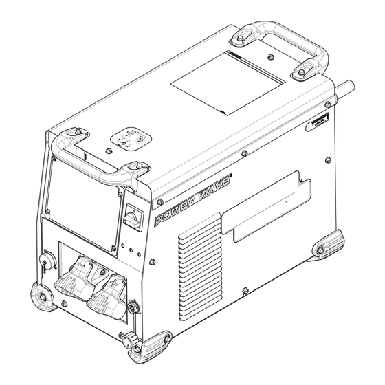
- Page 7 OPERATING TEMPERATURE RANGE The case of the Power Wave E500 has two lifting handles located on the front and rear of the case. The Power Wave E500 -10° C to + 55° C. has an IP23 rating that allows the machine to operate reliably in Output is de-rated for temperatures in excess of 40°...
- Page 8 POWER WAVE E500 INSTALLATION TECHNICaL SPECIFICaTIONS POWER SOURCES - INPUT VOLTAGE AND CURRENT Model Duty Cycle Input Voltage ± 10% Input Amperes Idle Power (W) Power Factor K3457-1 60% rating 380 / 400-415 / 3 / 50 / 60 37 / 35...
- Page 9 INSTALLATION POWER WAVE E500 INST LL TION LIFTING The Power Wave E500 has two handles that can be used to lift the machine. WARNING Both handles should be used when lifting the machine. When ELECTRIC SHOCK CAN KILL. using a crane or overhead device to lift using the handles, a lifting ONLY QUALIFIED PERSONNEL strap should be connected to both handles.
- Page 10 Electrode Voltage Sense Power Switch: Wire Feeder Receptacle (14-pin): Robotic Wire feeder Controls input power to the Power Wave E500. connector (for 4R100, 4R220, Power Feed 10 Robotic, etc.) Thermal LED: A yellow light that comes on when an over temperature situation occurs.
- Page 11 POWER WAVE E500 INSTALLATION CaSE BaCk CONTROLS Use a three-phase supply line. A 1.75 inch (45 mm) diameter access hole for the input supply is located on the case back. Remove the reconnect access panel located on the case back and connect L1, L2, L3 and ground according to the Input Supply Connection Diagram decal.
- Page 12 • SELECT THE APPROPRIATE SIZE CABLES PER THE Connect the electrode and work cables between the appropriate “OUTPUT CABLE GUIDELINES” BELOW. Excessive voltage output studs of the Power Wave E500 per the following drops caused by undersized welding cables and poor guidelines: connections often result in unsatisfactory welding •...
- Page 13 Wirefeeder control cable. Connection Between Power Source and Ethernet Networks The Power Wave E500 is equipped with an IP67 rated ODVA compliant RJ-45 Ethernet connector, which is located on the front panel. All external Ethernet equipment (cables, switches, etc.), as defined by the connection diagrams, must be supplied by the customer.
- Page 14 POWER WAVE E500 INSTALLATION...
- Page 15 POWER WAVE E500 OPERATION OPER TION GRAPHIC SYMBOLS THAT APPEAR ON THIS MACHINE OR IN THIS MANUAL RATED REDUCED INPUT POWER NO-LOAD VOLTAGE OPEN CIRCUIT VOLTAGE INPUT VOLTAGE OUTPUT VOLTAGE HIGH TEMPERATURE INPUT CURRENT MACHINE STATUS CIRCUIT BREAKER OUTPUT CURRENT...
-
Page 16: Arc Rays Can Burn Eyes And Skin
DUTY CYCLE The Power Wave E500 is capable of welding at a 100% duty cycle (continuous welding) at 450 Amps rated output. The 60% duty cycle rating is 500 amps (based off of a ten minute cycle –... -
Page 17: Basic Welding Controls
The POWER WAVE E500 then uses the WFS setting to adjust build/user is and must be solely responsible for welding the voltage and current according to settings contained in the program selection. - Page 18 Most pulse welding programs are synergic. As the wire feed When the wire feed speed changes, the POWER WAVE E500 speed is adjusted, the POWER WAVE E500 will automatically...
- Page 19 DC welding power source and the work clamp. Weld Fume Control Solutions. Lincoln Electric offers a wide variety of welding fume control solutions, ranging from portable systems easily wheeled around the shop to shop-wide central...
- Page 20 POWER WAVE E500 MAINTENANCE M INTEN NCE PERIODIC maINTENaNCE Thermal Protection WARNING Thermostats protect the machine from excessive operating temperatures. Excessive temperatures may be caused by a lack of ELECTRIC SHOCK can kill. cooling air or operating the machine beyond the duty cycle and •...
-
Page 21: Troubleshooting
POWER WAVE E500 TROUBLESHOOTING TROUBLESHOOTING How to Use troUblesHooting gUide WARNING Service and Repair should only be performed by Lincoln Electric Factory Trained Personnel. Unauthorized repairs performed on this equipment may result in danger to the technician and machine operator and will invalidate your factory warranty. - Page 22 Steady Green peripheral equipment connected to its ArcLink network. Occurs during power up or a system reset, and indicates the POWER WAVE E500 is mapping Blinking Green (identifying) each component in the system. Normal for first 1-10 seconds after power is turned on, or if the system configuration is changed during operation.
- Page 23 ERROR CODES FOR THE POWER WavE The following is a partial list of possible error codes for the POWER WAVE E500. A complete list of error codes is available in the Diagnostics Utility (included on the POWER WAVE Utilities or available at www.powerwavesoftware.com).
- Page 24 POWER WAVE E500 TROUBLESHOOTING Observe all Safety Guidelines detailed throughout this manual PROBLEMS POSSIBLE RECOMMENDED (SYMPTOMS) CAUSE COURSE OF ACTION BASIC MACHINE PROBLEMS Major physical or electrical damage is None evident when the sheet metal covers are Contact your local Lincoln Authorized Field removed.
- Page 25 POWER WAVE E500 TROUBLESHOOTING Observe all Safety Guidelines detailed throughout this manual PROBLEMS POSSIBLE RECOMMENDED (SYMPTOMS) CAUSE COURSE OF ACTION BASIC MACHINE PROBLEMS Thermal LED is ON. 1. Improper fan operation. 1. Check for proper fan operation. (Fans should run whenever output power is on.) Check for material blocking intake...
- Page 26 POWER WAVE E500 TROUBLESHOOTING Observe all Safety Guidelines detailed throughout this manual PROBLEMS POSSIBLE RECOMMENDED (SYMPTOMS) CAUSE COURSE OF ACTION WELD AND ARC QUALITY PROBLEMS General degradation of weld performance. 1. Wire feed problem. 1. Check for feeding problems. Check actual WFS vs.
- Page 27 POWER WAVE E500 TROUBLESHOOTING Observe all Safety Guidelines detailed throughout this manual PROBLEMS POSSIBLE RECOMMENDED (SYMPTOMS) CAUSE COURSE OF ACTION WELD AND ARC QUALITY PROBLEMS Excessively long and erratic arc. 1. Wire feed problem. 1. Check for feeding problems. Verify proper wire drive and gear ratio has been selected.
- Page 28 IP address information has been entered. NOTE: • The Power Wave E500 has a default static IP address of 192.16.8.0.2. • Verify no duplicate the IP addresses exist on the network. Connection Drops while welding.
- Page 29 POWER WAVE E500 DIAGRAMS FRONT OF MACHINE ~575V ~42V ~460V ~380V ~52V ~115V H3...
- Page 30 POWER WAVE E500 DIAGRAMS...
- Page 31 Index of Sub Assemblies - 12643 PART NUMBER DESCRIPTION P-1084-A INDEX OF SUB ASSEMBLIES P-1084-C CASE FRONT ASSEMBLY P-1084-D DIVIDER PANEL ASSEMBLY P-1084-E BASE & CENTER ASSEMBLY P-1084-F CASE BACK ASSEMBLY P-1084-G WRAPAROUND ASSEMBLY Power Wave E500 - 12643...
- Page 32 Index of Sub Assemblies - 12643 P-1084-A.jpg Power Wave E500 - 12643...
- Page 33 CABLE CONNECTOR CAP 9SCF000010 #10-24HN 9SE106A-1 LOCKWASHER 9SS26124 GROUND REFERENCE 9SS28393-3 OUTPUT SNUBBER ASBLY 9SS18858-5 SUPPRESSOR ASBLY 9SS9262-1 PLAIN WASHER 9SE106A-15 LOCKWASHER 9SCF000344 HEX HD SCREW 9SS30151 POSITIVE OUTPUT STUD LEAD 9SS18858-5 SUPPRESSOR ASBLY 9SS9262-1 PLAIN WASHER Power Wave E500 - 12643...
- Page 34 LOCKWASHER 9SCF000344 HEX HD SCREW 9SM19969-9 ETHERNET RECEPTACLE BULKHEAD 9SM19969-4 ETHERNET RECEPTACLE COVER 9SS28834-2 LINE SWITCH LEAD ASSEMBLY 9SS9225-68 THREAD FORMING SCREW (CUTTING) 9SS9262-183 PLAIN WASHER 9SS9225-66 SELF TAPPING SCREW 9SM19969-16 ETHERNET PATCH CABLE ASSEMBLY Power Wave E500 - 12643...
- Page 35 Case Front Assembly P-1084-C.jpg Power Wave E500 - 12643...
- Page 36 PLAIN WASHER 9SE106A-1 LOCKWASHER 9SCF000010 #10-24HN 9SS13490-157 CAPACITOR-ALEL24000100V+300/-10% 9SS11604-65 SET SCREW 9SS18250-955 PLUG & LEAD ASBLY 9SS9262-23 PLAIN WASHER 9SE106A-2 LOCKWASHER 9SCF000198 1/4-28HN 9SS22745-3 CAPACITOR INSULATION 9SS27974 CAPACITOR BRACKET 9SE106A-2 LOCKWASHER 9SCF000017 1/4-20HN 9SCF000010 #10-24HN Power Wave E500 - 12643...
- Page 37 INSULATOR 9ST10728-77 FUSE (4A) 9SS18491-1 MOV ASBLY 9SS18250-1074 PLUG & LEAD ASBLY 9SM26138 AUXILIARY TRANSFORMER & THERMOSTAT ASSEM 9SS13000-129 AUXILIARY TRANSFORMER 9ST13359-15 THERMOSTAT 9SS9225-32 THREAD FORMING SCREWS 9SS9262-98 PLAIN WASHER 9SS9225-68 THREAD FORMING SCREW (CUTTING) Power Wave E500 - 12643...
- Page 38 Divider Panel Assembly P-1084-D.jpg Power Wave E500 - 12643...
- Page 39 SELF TAPPING SCREW 9SM24999 OUTPUT RECTIFIER ASBLY 9SS9225-66 SELF TAPPING SCREW 9SS23730-3 SPACER 9SCF000015 1/4-20X1.00HHCS 9SS9262-98 PLAIN WASHER 9SE106A-2 LOCKWASHER 9SS28206-13 BRAIDED LEAD 9SCF000028 5/16-18X1.25HHCS 9SS9262-30 PLAIN WASHER 9SE106A-3 LOCKWASHER 9SCF000029 5/16-18HN 9SCF000028 5/16-18X1.25HHCS 9SS9262-30 PLAIN WASHER Power Wave E500 - 12643...
- Page 40 9SCF000040 5/16-18X.75HHCS 9SS9262-30 PLAIN WASHER 9SE106A-3 LOCKWASHER 9SCF000028 5/16-18X1.25HHCS 9SS9262-30 PLAIN WASHER 9SE106A-3 LOCKWASHER 9SCF000029 5/16-18HN 9SCF000040 5/16-18X.75HHCS 9SS9262-30 PLAIN WASHER 9SE106A-3 LOCKWASHER 9SG8986 SWITCHBOARD ASSEMBLY 9SS9225-66 SELF TAPPING SCREW 9SS18250-1063 PLUG & LEAD ASBLY Power Wave E500 - 12643...
- Page 41 Base & Center Assembly P-1084-E.jpg Power Wave E500 - 12643...
- Page 42 9SS8025-98 SELF TAPPING SCREW 9SS19999 CORD GRIP CONNECTOR 9ST14370-3 CONDUIT LOCKNUT 9SS9225-68 THREAD FORMING SCREW (CUTTING) 9SS9262-183 PLAIN WASHER 9SS9225-66 SELF TAPPING SCREW 9SS29938 RECONNECT PANEL COVER 9SS9225-68 THREAD FORMING SCREW (CUTTING) 9ST13259-4 GROUNDING DECAL Power Wave E500 - 12643...
- Page 43 Case Back Assembly P-1084-F.jpg Power Wave E500 - 12643...
- Page 44 THREAD FORMING SCREW (CUTTING) 9SS9262-183 PLAIN WASHER 9SG7802 RIGHT CASE SIDE 9SG7798 ROOF 9SS9225-68 THREAD FORMING SCREW (CUTTING) 9SG8035 WIRING DIAGRAM 9SS30277-2 WARRANTY DECAL 9SS27368-4 DECAL LE LOGO 9SS27468 POWERWAVE LOGO 9SS20601-6 WARNING DECAL 9SS28039-2 DECAL GREEN INITIATIVE Power Wave E500 - 12643...
- Page 45 Wraparound Assembly P-1084-G.jpg Power Wave E500 - 12643...
- Page 46 WARNING Do not touch electrically live parts or Keep flammable materials away. Wear eye, ear and body protection. electrode with skin or wet clothing. Insulate yourself from work and AVISO DE ground. Spanish PRECAuCION No toque las partes o los electrodos Mantenga el material combustible Protéjase los ojos, los oídos y el bajo carga con la piel o ropa moja-...
- Page 47 WARNING Keep your head out of fumes. Turn power off before servicing. Do not operate with panel open or Use ventilation or exhaust to guards off. remove fumes from breathing zone. AVISO DE Spanish PRECAuCION Los humos fuera de la zona de res- Desconectar el cable de ali- No operar con panel abierto o piración.
- Page 48 We respond to our customers based on the best information in our possession at that time. Lincoln Electric is not in a position to warrant or guarantee such advice, and assumes no liability, with respect to such information or advice.
Need help?
Do you have a question about the Power Wave E500 and is the answer not in the manual?
Questions and answers