Table of Contents
Advertisement
Air Conditioning Control System
Centralized Controller
AE-200A/AE-50A/EW-50A
AE-200E/AE-50E/EW-50E
Before using the controller, please read this Instruction Book carefully to ensure proper operation.
Retain this manual for future reference.
Contents
1. Safety precautions ..............................................................5
2. Introduction .........................................................................7
3. Parts to be used ................................................................13
4. Preparation .......................................................................15
5. Settings on the LCD ..........................................................31
6. Settings using Initial Setting Tool ......................................90
7. Settings using Web Browser for Initial Settings ..............136
8. Maintenance ...................................................................183
9. Troubleshooting ..............................................................188
10. Advance preparation .......................................................194
11. Explanation of terms .......................................................205
Appendix 1: Air-conditioner ON/OFF trial run .......................210
Appendix 2: Added functions ................................................214
<ORIGINAL>
Instruction Book
-Initial Settings-
WT07627X03
Advertisement
Table of Contents

Related Manuals for Mitsubishi AE-200A


Summary of Contents for Mitsubishi AE-200A
-
Page 1: Table Of Contents
<ORIGINAL> Air Conditioning Control System Centralized Controller AE-200A/AE-50A/EW-50A AE-200E/AE-50E/EW-50E Instruction Book –Initial Settings– Contents 1. Safety precautions ..............5 2. Introduction .................7 3. Parts to be used ..............13 4. Preparation ...............15 5. Settings on the LCD ............31 6. Settings using Initial Setting Tool ........90 7. - Page 2 Contents Safety precautions ......................5 1-1. General precautions ......................5 1-2. Precautions for relocating or repairing the unit ..............6 1-3. Additional precautions ......................6 Introduction ........................7 2-1. Terms used in this manual ....................7 2-2. Flow of the initial settings and trial run ................8 2-3.
- Page 3 5-4. Ventilation setting ......................84 5-4-1. Night purge ......................84 5-5. User Information ........................ 87 5-5-1. Maintenance User ....................87 5-5-2. Building Manager ....................88 Settings using Initial Setting Tool ................. 90 6-1. Flow of the initial settings on Initial Setting Tool ..............90 6-2.
- Page 4 7-2-3. Measurement ....................... 164 7-2-4. Energy Management Settings ................168 7-3. Functions 2 ........................170 7-3-1. Set Temperature Range Limit ................170 7-3-2. Night Mode (quiet operation) Schedule ..............171 7-3-3. System-changeover ..................... 172 7-4. Functions 3 ........................174 7-4-1. External Temperature Interlock ................174 7-4-2.
-
Page 5: Safety Precautions
1. Safety precautions ►Observe these precautions carefully to ensure safety. ►After reading this manual, pass the manual on to the end user to retain for future reference. ►The user should keep this manual for future reference and refer to it as necessary. This manual should be made available to those who repair or relocate the units. -
Page 6: Precautions For Relocating Or Repairing The Unit
Consult your dealer for the proper disposal of the controller. Improper disposal will pose a risk of environmental pollution. 1-2. Precautions for relocating or repairing the unit The controller must be repaired or moved only by qualified personnel. Do not disassemble or modify the controller. -
Page 7: Introduction
Any connected air conditioning systems can be operated or monitored on the AE-200A/AE-50A/AE-200E/AE-50E’s LCD or the Web browser. Each AE-200A/AE-50A/EW-50A/AE-200E/AE-50E/EW-50E can control up to a total of 50 indoor units and other equipment. By connecting AE-200A/AE-200E (main controller) and AE-50A/AE-50E/EW-50A/EW-50E (sub controllers), up to 200 indoor units and other equipment can be controlled. -
Page 8: Flow Of The Initial Settings And Trial Run
2-2. Flow of the initial settings and trial run This explains one example of settings procedures. Prepare a PC with which to use the Initial Setting Preparation of the PC Tool and Web Browser for Initial Settings. (See section 10-1.) Settings with each centralized controller (Common: See sections 4-2 and 4-3. - Page 9 Initial settings for AE-200/AE-50/EW-50 can be configured on the LCD, Initial Setting Tool, and Web Browser for Initial Settings. Each has specific characteristics as below. • LCD Method for setting the AE-200/AE-50/EW-50 from the AE-200’s LCD. Configuration of initial settings for single AE-200 systems is possible. Methods of setting from the LCD are explained in section 5 “Settings on the LCD”.
- Page 10 The settings ranges for each of these settings are as below. AE-200 system No. 1 AE-200 EW-50 EW-50 EW-50 EW-50 M-NET M-NET M-NET M-NET Initial Setting Tool AC units AC units AC units AC units or Web Browser for Initial Settings Initial Setting Tool AE-200 system No.
-
Page 11: Functions That Can Be Set
2-3. Functions that can be set The functions that can be set by using the LCD, Initial Setting Tool, and Web Browser for Initial Settings are different. See the table below to check the functions to be used, and configure the settings combining multiple initial settings methods. - Page 12 Initial Setting Web Browser for Setting item Description Tool Initial Settings Set Temperature Range Set to restrict the local remote Limit controller set temperature range. Set to switch outdoor units to quiet Night Mode (quiet operation) operation for a certain period of Schedule time.
-
Page 13: Parts To Be Used
3. Parts to be used This section explains parts required for initial settings. Refer to the Installation Manual for parts required for installation of AE-200/AE-50/EW-50. 3-1. Separately sold parts Item Description Required to operate functions that require a license. License Required number Register for each of AE-200/AE-50/EW-50. -
Page 14: Pc Requirements
3-3. PC requirements The operating environment for the PC with which to use the Initial Setting Tool and Web Browser for Initial Settings is as below. Item Requirements 1 GHz or better (at least 2 GHz recommended) Memory 1 GB Screen resolution 1024 x 768 or better (at least 1366 x 768 recommended) Windows 7 SP1 (32bit/64bit), Windows 8.1 (64bit), Windows 10 (64bit) -
Page 15: Preparation
4. Preparation 4-1. Logging in to the Web Browser for Initial Settings Check that the Web Browser for Initial Settings can be logged in. (1) Enter the web page address in the address field of the Web browser as follows: http://[IP address of each AE-200, AE-50, or EW-50]/init/administrator.html Press the [Enter] key. - Page 16 (2) Enter the user name and the password in the login screen, and click [Login]. A setting screen will appear. The table below shows the default user names, passwords, and functions that are available for maintenance users and building managers. Default Default User...
- Page 17 (HTTPS connection) AE-200/AE-50/EW-50 can encrypt communication data using HTTPS (SSL). When connecting the AE-200/AE-50/EW-50 to the LAN that is accessible to the general public, it is recommended that the following settings be made so that the units are monitored and controlled on the encrypted web page. Note: Depending on the operating system or the Java version, HTTPS encrypted communication may not be enabled properly.
- Page 18 (6) Choose [Place all certificates in the following store] and click the [Browse...] button. Select [Trusted Root Certification Authorities], click [OK], and then click [Next]. (7) Click [Finish] on completing the Certificate Import Wizard. (8) Click [Yes] on the security warning to install the certificate. (9) Certificate import process starts.
-
Page 19: Date And Time Setting
4-2. Date and time setting Set the date and time for the AE-200/AE-50/EW-50. There are two ways to set the date and time — from the AE-200’s LCD, and individually from the AE-200/AE-50/EW-50 Web Browser for Initial Settings. If an expansion controller is connected in an AE-200 system, connect the AE-200 to the expansion controller over a LAN, then set the date and time from the AE-200. - Page 20 [2] When setting date and time on the AE-200/AE-50/EW-50’s Web Browser for Initial Settings Click [Initial Settings] in the menu bar, and then click [Date and Time] to access the date and time settings screen. Set the current date and time, and then click [Save Settings]. Note: The date and time settings may not be accessible if logged in as a building manager.
-
Page 21: Ip Address Settings
4-3. IP address settings Set AE-200/AE-50/EW-50 IP addresses, and configure the expansion controller connection settings on the AE-200’s LCD. For an AE-200 system, set using the following procedure. No expansion controller Expansion controller connected connected Set the IP address of AE-50 on the LCD or the Web Browser for Initial Settings, and set the IP address of EW-50 on the IP address setting of AE-50/EW-50 Web Browser for Initial Settings. - Page 22 [1] Settings for connecting the AE-200/AE-50/EW-50 to a dedicated LAN (1) Enter the AE-200, AE-50, or EW-50’s IP address in the [IP Address] field. If the LAN has been newly set up, allocate IP addresses to the AE-200 units in a sequential order starting with [192.168.1.1]. For example, the first AE-200 unit will have an IP address of [192.168.1.1], the second AE-200 unit will have an IP address of [192.168.1.2] and so on.
- Page 23 [2] Settings for connecting the AE-200/AE-50/EW-50 to an existing LAN (1) When connecting the AE-200/AE-50/EW-50 to an existing LAN, consult the system administrator to decide the IP, subnet mask, and gateway addresses. [Existing LAN System example] Backbone LAN Gateway Gateway 10.1.1.250 10.1.2.250 AE-200...
-
Page 24: Setting Ip Addresses Of Ae-50/Ew-50
4-3-1. Setting IP addresses of AE-50/EW-50 Set the AE-50/EW-50 IP addresses. Settings screens will differ depending on the unit model. AE-50: AE-50’s LCD or AE-50’s Web Browser for Initial Settings EW-50: EW-50’s Web Browser for Initial Settings Note: Set IP address for “LAN1.” ®... - Page 25 [2] When setting on the AE-200/AE-50’s Web Browser for Initial Settings Click [Initial Settings] in the menu bar, and then click [Basic System] to access the Basic System settings screen. Note: The Basic System settings may not be accessible if logged in as a building manager. Network Settings Set the IP address and subnet mask of the...
-
Page 26: Setting Ip Addresses Of Ae-200
4-3-2. Setting IP addresses of AE-200 Set the AE-200 IP address and the expansion controller connection. [1] AE-200 initial start-up for a system without connection to an AE-50/EW-50 controller (1) After the power is turned on, a language selection screen will appear. - Page 27 (2) Touch the [Unit Info.] and [Unit Info. 2] tabs. Unit Info. Referring to section 5-1-4 “Unit Information”, make necessary basic settings, and then touch [Save Settings]. Note: Make sure to set the [System Exp] setting for the AE-200 to [Expand].
-
Page 28: Software Update
4-4. Software Update Refer to the AE-200/AE-50 Installation Manual for how to update the software for AE-200/AE-50. Refer to the EW-50 Installation and Instructions Manual for how to update the software for EW-50. WT07627X03... -
Page 29: License Registration For Optional Functions
4-5. License registration for optional functions There are two ways to register the license — from the AE-200’s LCD, and individually from the AE-200/AE-50/ EW-50 Web Browser for Initial Settings. Please contact your dealer as regards optional functions and purchasing license numbers. Note: After the “Integrated Centralized Control Web”... - Page 30 [2] When registering a license on the AE-200/AE-50/EW-50’s Web Browser for Initial Settings Note: The current date and time settings are required for license registration. Refer to section 7-1-1 “Date and Time” for date and time settings. Note: The license registration is required for each AE-200/AE-50/EW-50. (1) On the login screen, click [Registration of Optional Functions].
-
Page 31: Settings On The Lcd
5. Settings on the LCD 5-1. Initial Settings 5-1-1. Logging in to the Initial Settings menu (1) Touch [ ] to display the login window. (2) Enter the user name and the password on the keyboard screen (See [1] “Keyboard screen”), and touch [Login]. [Initial Settings] menu screen will appear. -
Page 32: Locking The Screen
[1] Keyboard screen Arrow The entered characters will appear here. Touch to move the cursor. Delete Touch to delete one character to the left of the cursor. Touch to display the keyboard for entering capital Cancel alphabetic characters. Touch to undo the changes made and return to the previous screen. -
Page 33: Date And Time
5-1-3. Date and time Touch [Initial Settings] in the menu bar, and then touch [Date and time]. Set the current date and time, and then touch [Save Settings]. Note: The date and time settings may not be accessible if logged in as a building manager. Note: The date and time settings made on this screen will be reflected on all the units in the M-NET system, all connected AE-50/EW-50 units, and the AE-200 units whose [Time Master/Sub] setting is set to [Sub]. - Page 34 Note ● Message that will appear when the date and time have been reset If the power supply is cut off for a long time due to power failure or other reasons, the date and time will be reset, and the following popup message will appear when the power is turned on next.
-
Page 35: Unit Information
5-1-4. Unit Information Touch [Initial Settings] in the menu bar, and then touch [Unit Info.] or [Unit Info. 2]. Make necessary basic system settings such as unit settings, display format, sound/brightness settings, use or non- use of test run, and display or non-display of room temperature/humidity, and then touch [Save Settings]. Note: The Unit Information settings may not be accessible if logged in as a building manager. - Page 36 (2) Touch the [Unit ID] button to display the keyboard. Enter the unit ID in 6 figures. Use this setting to manage the multiple unit IDs. The unit ID entered here will be used on the screen of the software that controls multiple AE-200 units and will also be used as a sender ID in the error notification e-mail and e-mail alarm.
- Page 37 (8) In the [Brightness] section, make the Show/Hide setting for the brightness/darkness status that is detected by the built-in brightness sensor on the ME remote controller (North America: PAR-U01MEDU, Europe: PAR- U02MEDA). Select [Hide] not to display the brightness/darkness icons on the [Floor] or [Block] display. Select [ ] (yellow) to display the brightness icon when the brightness level in the room reaches the predetermined brightness level.
- Page 38 (2) In the [Temperature display] section, select the desired display option for the room temperature or the set temperature to be used on the [Floor] or [Block] display. Select [Room temp. (Always)] to display the room temperature at all times, [Room temp. (During operation)] to display the room temperature only during operation, [Set temp.] to display the set temperature at all times, [Room temp.(Always)/Set temp.] to display both the room temperature and set temperature at all times, [Room temp.(During op.)/Set temp.] to display the room temperature only during operation and to display the set...
-
Page 39: Network
5-1-5. Network Touch [Initial Settings] in the menu bar, and then touch [Network]. Make necessary basic system settings such as LAN settings, M-NET settings, and external input settings for each AE-200, AE-50, and EW-50, and then touch [Save Settings]. A message will appear asking whether or not to restart the controller. - Page 40 (When connecting one or more expansion controllers) Detect communication error IP address Save Settings Touch to go to the previous Touch to save the changes page. made. [1] LAN1 Settings LAN1 settings vary depending on whether the AE-200/AE-50 is connected to a dedicated LAN or an existing LAN. See the sections below for how to set the AE-200/AE-50 IP addresses, subnet mask, and gateway addresses.
- Page 41 (4) When monitoring the system remotely or using e-mail function via a dial-up router, enter the router IP address in the [Gateway] field. Leave the [Gateway] field blank when not connecting a dial-up router. [192.168.1.254] is recommended for use as the IP address of the dial-up router. Refer to the dial-up router instruction manual for details of how to set the IP address.
- Page 42 (3) Select [SC/RC] to prohibit the operation from both the sub system controllers and the remote controllers. Select [RC Only] to prohibit the operation only from the remote controllers. [4] External Input Setting Using the external signal input function, the following types of collective operations can be performed for all connected air conditioning units: Demand level, Emergency stop, ON/OFF operation, and Prohibit/Permit local remote controller operation.
-
Page 43: Groups
5-1-6. Groups Touch [Initial Settings] in the menu bar, and then touch [Groups]. Register the groups of air conditioning units, LOSSNAY units (ventilators), Air To Water (PWFY) units, AHC, HWHP (CAHV, CRHV) units, chiller units, or general equipment to be connected to the AE-200/AE-50/EW-50, and then touch [Save Settings]. - Page 44 [2] Registering air conditioners, Air To Water (PWFY) units, LOSSNAY units, HWHP (CAHV, CRHV) units, or chiller units to a group (1) To register air conditioners, Air To Water (PWFY) units, LOSSNAY units, HWHP (CAHV, CRHV) units, and chiller units to each group, touch the “Unit selection” button under the target group name.
- Page 45 [4] Registering system controllers to a group (1) To register system controllers to a group, touch the “System controller registration” button under the target group name. A screen to select the units will appear. Select the address numbers of the system controllers to be registered.
- Page 46 [6] Registering general equipment to a group (1) To register general equipment to a group, touch the “Unit selection” button under the target group name. A screen to select the units will appear. Select [General Equipment (via PAC-YG66DCA)] in the [Model] section, and select the unit address of the DIDO controller (PAC-YG66DCA) that is connected to the general equipment to be registered.
-
Page 47: Hw Supply
5-1-7. HW Supply Touch [Initial Settings] in the menu bar, and then touch [HW Supply]. Set the address, group names, and detail settings for each group of HWHP (QAHV) unit that is connected to AE-200. Touch [Save Settings] when done. Note: Group settings for HWHP (QAHV) units can only be set on the AE-200’s LCD. - Page 48 (2) To change the unit icon to be used, touch the icon. A screen to select an icon will appear. Select an icon to be used, and touch [OK]. [3] Initial startup of HWHP (QAHV) (1) When done registering all HW Supply unit groups, touch [Save Settings].
- Page 49 Note: Specify the “Operation ON sensor” with a number equal to or smaller than that of the “Operation OFF sensor.” Note: Operation will be carried out as shown in the figure below when “Sensor 1” is set for “Operation ON sensor” and “Sensor 3”...
-
Page 50: Interlocked Lossnay
5-1-8. Interlocked LOSSNAY The ON/OFF status of the LOSSNAY unit can be interlocked with the operation of indoor units. Touch [Initial Settings] in the menu bar, and then touch [Interlock]. Set the interlocking conditions for each AE-200, AE-50, and EW-50, and then touch [Save Settings]. Note: The Interlocked LOSSNAY settings may not be accessible if logged in as a building manager. -
Page 51: Blocks
5-1-9. Blocks By making block settings, multiple groups in a given block can be collectively monitored or operated. Touch [Initial Settings] in the menu bar, and then touch [Blocks]. Register the groups to each block, and then touch [Save Settings]. Note: Some settings may not be accessible if logged in as a building manager. -
Page 52: Em Blocks
5-1-10. EM Blocks Carrying out EM block (energy management block) settings enables batch status monitoring and operation of multiple blocks covering AE-200/AE-50/EW-50. Touch [Initial Settings] in the menu bar, and then touch [EM Blocks]. Register the blocks to each EM block, and then touch [Save Settings]. -
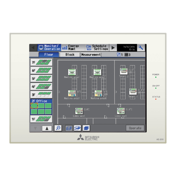
Page 53: Floor Layout
5-1-11. Floor Layout The floor layout on the [Floor] display under the [Monitor/Operation] menu can be changed, and the display position of the groups on the floor can be changed. Touch [Initial Settings] in the menu bar, and then touch [Floor Layout]. All unit groups that are under the control of both AE-200 and AE-50 can be displayed on the Floor Layout screen of the AE-200. - Page 54 The display range of the area on the [Floor Layout] screen vary, depending on the selected floor layout. Floor layout Display area Floor layout Display area (3) Touch the “Floor level name” button to display the Floor level name keyboard. Enter the floor level name in 3 alphanumeric Floor name or symbol characters or less.
- Page 55 Floor File name Floor File name floor_01.gif floor_06.gif floor_02.gif floor_07.gif floor_03.gif floor_08.gif File name floor_04.gif floor_09.gif floor_05.gif floor_10.gif *1 The floor numbers in the table are not the actual floor level name, but the number counted from the bottom on the [Floor Layout] screen.
- Page 56 [3] Moving a group to other areas (1) On the [Floor Layout] screen, touch the group icon to be moved. The selected group icon will appear with an orange frame. Note: When the “Unassigned groups” button is touched, groups that have not been assigned to any area will appear in the order of their group numbers.
- Page 57 (4) Touch [Save Settings]. Note: To move the pasted group icon within the area, refer to [4] “Moving a group within the area” below. [4] Moving a group within the area Note: It is recommended to use a commercially available touch pen. (1) On the [Floor Layout] screen, touch the group icon to be moved.
-
Page 58: System View
5-1-12. System View Refrigerant system information (connection information of outdoor and indoor units) can be checked for each AE-200, AE-50, and EW-50. Touch [Initial Settings] in the menu bar, and then touch [System View]. Note: This screen shows the information of the units that have been registered to a group and have started up successfully. Note: The [Controller] setting will appear (only on the AE-200’s LCD) when the [System Exp] setting on the [Unit Info.] screen is set to [Expand]. -
Page 59: Advanced Settings
5-1-13. Advanced settings Touch [Initial Settings] in the menu bar, and then touch [Advanced]. Make necessary settings, and then touch [Save Settings]. Note: The Advanced settings may not be accessible if logged in as a building manager. Time Master/Sub Old model compatibility Hold type mode Schedule: Season setting... - Page 60 If the [Hold type] is set to [Normal], the [Hold] setting can be cancelled from AE-200/AE-50, other system controllers, or remote controllers. Note: The Hold function can be used on the AE-200A/AE-50A, but not on the AE-200E/AE-50E. Note: The Hold function cannot be used on general equipments.
-
Page 61: Function1
Important ● The amount of electricity that is actually used may exceed the maximum power demand due to unexpected problems such as controller malfunctions or broken transmission cables. Mitsubishi Electric will not be responsible for exceeding the maximum power demand. - Page 62 5-2-1-1. Peak Cut method Touch the [Settings] tab in the Peak Cut control settings screen. [PLC Software for Demand Input] [Electric Amount Count Software] Reads electric Pulse Demand level is Demand level energy values. input. signal is sent. AE-200 AE-200 Electric Amount Pulse-watt- Demand-Input...
- Page 63 [From external system] Demand level Pulse signal is sent. AE-200 PLC etc. Pulse-watt- hour meter AE-50 AE-50 Maximum ten AE-200/AE-50/EW-50 units AE-50 (A) When the Peak Cut method [PLC Software for Demand Input] is selected 1st page Peak Cut method Initialize IP address of PLC Temperature difference...
- Page 64 (3) In the [Temperature difference between set point and inlet] section, a temperature differential can be set to between 3 and 9 as necessary. The Peak Cut control setting that corresponds to the control level 0 will be disregarded for the indoor unit groups in which the temperature difference between the set temperature and the room temperature is greater than the specified temperature differential.
- Page 65 (3) Touch the [DI Board] or [Pulse Unit] button to open the window to select the DI board number to which the watt- hour meter is connected, and the terminal number. If the watt-hour meter is connected to terminal 2 on a DI board 1, select 1-2.
- Page 66 (C) When the Peak Cut method [PI Controller] is selected 1st page Peak Cut method Watthour meter Save Settings Temperature difference between set point and inlet 2nd page Control levels Save Settings WT07627X03...
- Page 67 (1) Touch the [Watthour meter] button to open the window to select the PI controller to which the watt-hour meter used for the Peak Cut function is connected. Note: Only the watt-hour meters that have been registered on the [Measurement] screen are selectable. (Refer to section 5-2- 2 “Measurement”...
- Page 68 (1) In the [IP address] field, enter the IP address of the AE-200/AE-50/EW-50 that uses one of the following. - Built-in Pulse Input (PI) - PI controller (PAC-YG60MCA) - External contact input (Refer to (E) “When the Peak Cut method [External Contact point input] is selected” for details.) Note: As the control level is obtained every minute from the AE-200/AE-50/EW-50 that uses a built-in Pulse Input (PI) or a PI controller (PAC-YG60MCA), the control will be late for up to one minute on the AE-200/AE-50 whose Peak Cut method...
- Page 69 (F) When the Peak Cut method [From external system] is selected Peak Cut method Temperature difference between set point and inlet Save Settings (1) In the [Temperature difference between set point and inlet] section, a temperature differential can be set to between 3 and 9 as necessary.
- Page 70 5-2-1-2. Unit settings Touch the [Air-con] tab in the Peak Cut control settings screen. (1) Control details for blocks of indoor units Follow the instructions below to make the Peak Cut control settings for each control level for given blocks of indoor units.
- Page 71 (2) For each control level, set the total time in which When [6] minutes is selected Control time the Peak Cut control is performed during every 30 8 10 15 18 20 23 25 minutes. Each Peak Cut control is performed for three Group 1 minutes.
- Page 72 Note: For heat pump outdoor units and City Multi S series (PUMY) outdoor units, leave the default setting [100%] as it is not to activate the capacity-save control. However, [50%] though [100%] can be set on the following models. PUMY-P**KM or later PUMY-P**KM-A or later PUMY-P**HMC-S or later PUMY-P**HMC-C or later...
-
Page 73: Measurement
5-2-2. Measurement Measurement settings must be made to use temperature sensors, humidity sensors, and metering devices. Touch [Function1] in the menu bar, and then touch [Measurement]. Set the measurement settings for each AE-200 and AE-50, and then touch [Save Settings]. Note: The measurement settings may not be accessible if logged in as a building manager. - Page 74 (3) Touch the “Sensor name” button to display the keyboard. Enter the name of the sensor in 20 characters or less. Note: The following characters cannot be used: <, >, &, “, or ‘ (4) Touch the “Temperature or humidity sensor settings” Selection of temperature or humidity sensor icon button to display the sensor settings screen.
- Page 75 [2] Registering PI controllers and metering devices Important ● The built-in Pulse Input (PI) settings cannot be made on the TG-2000A. ● The built-in Pulse Input (PI) cannot be used for the electricity charge apportioning function of TG-2000A. Follow the instructions below to make the system settings of the metering devices. Up to four metering devices can be connected to a PI controller (PAC-YG60MCA) or CN7 of AE-200/AE-50/EW-50.
- Page 76 (5) Touch the “Measurement unit” button to select the measurement unit. Note: The measurement unit can be selected from [kWh], [m3], [MJ], [--(no unit)], or [(blank)]. Select the blank when not using a metering device. Important ● Set the pulse value according to the metering device to be used. To ensure proper settings, first check the value measured by the metering device and the value counted by the built-in Pulse Input (PI) or the PI controller (PAC- YG60MCA).
-
Page 77: Energy Management
5-2-3. Energy Management On the Energy Management screen, make the settings for the energy-control-related items that appear on the screens under the [Energy Mgmt] menu, such as temperature sensor to measure the outdoor temperature with, electricity meters that are used for acquiring the data to display the trend graph of indoor unit electricity consumption, and also the mode that are used for apportioning indoor unit electricity consumption. - Page 78 Note: To deselect the selection, select [-- --]. Note: “FAN operation time” is the cumulative duration of time in which the indoor unit is powered on. Note: “Thermo-ON time” is the cumulative duration of time in which the refrigerant is flowing into the indoor unit. Note: “Capacity save amount”...
-
Page 79: Function2
5-3. Function2 5-3-1. External Temperature Interlock Based on the temperature difference between the set temperature and the outdoor temperature, the set temperature can be adjusted automatically. Making this control setting on the air conditioning unit at an entrance of a building prevents extreme temperature change from distressing our bodies and sending us into shock. - Page 80 (2) In the [Control levels] section, select a maximum temperature value for each group to be added to or sabtracted from the set temperature. For example, when [±4°C] (±8°F) is selected and the set temperature for the Cool or the Dry mode is set to 24°C (75°F), the set temperature will be adjusted to a maximum of 28°C (83°F) based on the temperature difference between the set temperature and the outdoor temperature.
- Page 81 When the External Temperature Interlock function is active, the set temperature will be adjusted as shown below. ■ “Cool” and “Dry” modes ■ Outdoor temperature Set temperature after being adjusted when [Control levels] is set to [±4°C] (±8°F) Set temperature Time Outdoor temperature conditions Set temperature after being adjusted...
-
Page 82: Night Setback Control
5-3-2. Night Setback Control The Night Setback Control function (hereafter abbreviated as Setback Control) prevents indoor condensation by performing heating operation automatically when the room temperature goes outside of the specific range during the night. Touch [Function2] in the menu bar, and then touch [Setback]. Heating operation starts when a given group is stopped and the room temperature drops below the specified minimum temperature. - Page 83 (2) Touch the “Temperature range” button to display the settings screen. Set the maximum and minimum temperatures for each group. For example, if [Control Time] is set to [01:00 - 05:00] and “Temperature range” is set to [12°C - --°C] ([53°F - --°F]), heating operation starts automatically when the room temperature drops below the set temperature 12°C (53°F) between 1:00 and 5:00.
-
Page 84: Ventilation Setting
5-4. Ventilation setting 5-4-1. Night purge During summer, the Night purge function draws cooler outside air into the room to suppress temperature rises at night. This energy conservation reduces the load when air conditioning starts the next morning. Note: During the Night purge operation, LOSSNAY units operate in the Bypass mode. Note: Night purge setting cannot be made from AE-200 for the LOSSNAY units that are connected to the AE-50/EW-50 in communication error. - Page 85 Setting item Setting method Remarks Touch [Available] to enable the Night purge Night purge settings, and [Not [Available]/[Not Available] Available] not to. <Example> When the settings are made as follows, the Night purge control starts at 23:00 on Monday and ends at 6:00 on Tuesday. Touch one or more days on Days of the week: Monday which the Night purge control is...
- Page 86 Night purge control time chart sample The time chart when conditions below meet is as follows. Setting value 2 Setting value 1 Setting value 3 Setting value 4 Starting condition Condition #1: LOSSNAY units stop at 20:00. Condition #2: Between the start time 1:00 (setting value 1) and the end time 6:00 (setting value 2) Condition #3: LOSSNAY units detected the outdoor temperature threshold 17ºC (setting value 3) or higher in the past 24 hours.
-
Page 87: User Information
5-5. User Information 5-5-1. Maintenance User On the [Maintenance User] screen, the user names and passwords of maintenance users can be changed. Touch [User Info] in the menu bar, and then touch [Maintenance User]. Note: The Maintenance User settings are not be accessible if logged in as a building manager. Note: The Maintenance User settings are required for each AE-200/AE-50/EW-50. -
Page 88: Building Manager
5-5-2. Building Manager On the [Building Manager] screen, the user names and passwords of building managers can be changed, and the available functions for building managers can be limited. For example, you can allow building managers to change the group name settings when the tenant is changed, or disallow them to change the basic system settings such as unit settings or network settings. - Page 89 Table. Available Function List Function Content Date and time Refer to section 5-1-3 “Date and time” for details. Unit Info. Refer to section 5-1-4 “Unit Information” for details. Advanced Refer to section 5-1-13 “Advanced settings” for details. Network Refer to section 5-1-5 “Network” for details. Group Name Groups Refer to section 5-1-6 “Groups”...
-
Page 90: Settings Using Initial Setting Tool
6. Settings using Initial Setting Tool 6-1. Flow of the initial settings on Initial Setting Tool Follow the procedures from step ③ onwards to make the initial settings for the apportioned electricity billing function. As shown in flow ① below, settings data can be created beforehand at another location, such as office, to send it to the centralized controller on the day of the trial run. -
Page 91: General Descriptions Of Initial Setting Tool
6-2. General descriptions of Initial Setting Tool This section explains operation methods that are common to all setting screens of Initial Setting Tool. 6-2-1. Starting up the Initial Setting Tool AE-200 Initial Setting Tool The screen below will appear when the Initial Setting Tool is started up. Click to newly create a settings file. -
Page 92: Screen Configurations And Common Items
6-2-2. Screen configurations and common items ① Tool bar ② Tab (Upper) (Lower) ③ Target centralized controller ④ Setting area ⑥ [Back] ⑤ [Save] Function Operation method Description Tool bar Operations such as to create, save, Refer to section 6-2-3 “List of tool bar load and send the settings files, and to operations”. -
Page 93: List Of Tool Bar Operations
6-2-3. List of tool bar operations File Creates, opens (loads) and saves settings files, and saves settings files with another name. [10] Help Displays the version of this software. [11] [4] Data acquisition Option Acquires settings status of the Able to select the temperature display format centralized controller. - Page 94 [4] Data acquisition Loads the AE-200/AE-50/EW-50 settings data on the Initial Setting Tool. Note: When changing the AE-200/AE-50/EW-50 settings, make sure to select [Acquire data] first. (1) Click [Basic Settings] > [System Configuration] and enter the IP address of the AE-200/AE-50/EW-50 from which the data is to be acquired.
- Page 95 [8] Output - Check sheet for billing function trial run Click [Option] > [Output - Check sheet for billing function trial run] in the tool bar to output the check sheet used for billing function trial runs. Note: The check sheet will be output based on the settings on the Initial Setting Tool. If the settings on the AE-200/AE-50/EW-50 and the Initial Setting Tool are not the same, the billing function trial will not run correctly.
- Page 96 [10] Help Click [Help] > [About] in the tool bar to display the version of the current Initial Setting Tool. [11] Exit Click [File] > [Exit] in the tool bar to exit the Initial Setting Tool. WT07627X03...
-
Page 97: Unit Address Selection Screen
6-2-4. Unit address selection screen On unit address selection screen and group registration screen displayed from the group settings screen, the selectable unit addresses and groups will be displayed. When an icon is clicked and selected, the background will change to yellow-green. To deselect an icon, click the icon again and it will then turn into deselected status (the background will change to light gray). -
Page 98: Preparation And Flow Of The Initial Setting Tool
6-2-6. Preparation and flow of the Initial Setting Tool To change the AE-200/AE-50/EW-50 settings (for systems with initial settings already made), make sure to first acquire data of the settings status using the Initial Setting Tool and then follow the procedure below. If you follow a different procedure, the settings may not be correctly made. -
Page 99: Basic Settings
6-3. Basic settings 6-3-1. System Configuration settings Make the configuration settings of centralized controllers and expansion controllers on the Initial Setting Tool. Click [Basic Settings] > [System Configuration] to access the system configuration settings screen. Note: Connection settings can be made for up to 40 centralized controllers. AE-200 units set as the [AE-200 (Billing)] or [AE-200 (No M-NET)] will not be included in this 40 controllers. -
Page 100: Basic System Settings
6-3-2. Basic System settings Click [Basic Settings] > [Basic System] to access the basic system settings screen. Make necessary basic system settings such as unit settings and M-NET settings for each centralized controller. Target centralized controller Select the connected centralized controller whose basic settings are to be M-NET Settings made. - Page 101 [2] M-NET settings (1) Enter [0] in “M-NET Address” (unless otherwise specified). (2) When the local remote controller operation is prohibited on the centralized controller, this setting determines the scope of its applicability. Select [SC/RC] to prohibit the operation from both the sub system controllers and the remote controllers.
- Page 102 If the “Hold type” is set to [Normal], the [Hold] setting can be cancelled from AE-200/AE-50/EW-50, other system controllers, or remote controllers. Note: The Hold function can be used on the AE-200A/AE-50A/EW-50A, but not on the AE-200E/AE-50E/EW-50E. Note: The Hold function cannot be used on general equipments.
- Page 103 (6) In “Filter Sign Display”, select [ON] to display the filter sign on the Monitor/Operation screen, and select [OFF] not to. When the “Filter Sign Display” is set to [OFF], the filter sign will not appear on the Monitor/Operation screen even when the indoor unit detects a filter cleaning signal.
- Page 104 (10) In “Brightness sensor display”, make the Show/Hide setting for the brightness/darkness status that is detected by the built-in brightness sensor on the ME remote controller (North America: PAR-U01MEDU, Other countries: PAR-U02MEDA). Brightness icon Darkness icon (Gray) (Yellow) Select [Hide] not to display the brightness/darkness icons on the Monitor/Operation screen. Select [Show bright icon] to display the brightness icon when the brightness level in the room reaches the predetermined brightness level.
-
Page 105: Unit Settings
6-4. Unit settings This section explains how to make unit settings on the Initial Setting Tool. 6-4-1. Group settings Note: Each group can contain up to 16 air conditioners. Note: Air conditioners (City Multi indoor unit), Air conditioners (A-control), LOSSNAY units, Air To Water (PWFY) units, HWHP (CAHV, CRHV) units, chiller units, and general equipment groups cannot be combined in one group. - Page 106 (9) When [General Equipment (via PAC-YG66DCA)] is selected, in “Monitor”, select which status will be used to reflect the units’ ON/OFF status to the unit icons on the Monitor/Operation screen. Select [Output status] to use the status that is sent to the general equipment, and [Input status] to use the status that is sent from the general equipment.
-
Page 107: Refrigerant System Settings
6-4-2. Refrigerant System settings Refrigerant system information (connection information of outdoor, sub outdoor, and indoor units) can be set. (1) Click [Unit Settings] > [Refrigerant System] to access the refrigerant system settings screen. Target centralized Indoor unit registration controller Click to display the screen Select the connected for registering the indoor centralized controller whose... -
Page 108: Interlocked Lossnay Settings
6-4-3. Interlocked LOSSNAY settings The ON/OFF status of the LOSSNAY or OA Processing units can be interlocked with the operation of indoor units. Note: The ON/OFF status of the indoor units are not interlocked with the ON/OFF status of the LOSSNAY unit. (1) Click [Unit Settings] >... -
Page 109: Block Settings
6-4-4. Block settings By making block settings, multiple groups in a given block can be collectively monitored or operated on the AE-200’s LCD and the Integrated Centralized Control Web. Note: The ventilation will stop when the Peak Cut control runs for the LOSSNAY units or OA Processing units that perform Night purge operation. -
Page 110: Energy Management Block Settings
6-4-5. Energy management block settings Make the settings for the energy management block (tenant) used as collective unit for the apportioned electricity billing function. [1] General descriptions (1) What is energy management block (tenant)? • An energy management block (tenant) is the unit used for displaying and outputting charge calculation results. - Page 111 [2] Energy management block settings (1) Click [Unit Settings] > [Energy Management Block] to access the energy management block settings screen. Target centralized Member LOSSNAY controller with heater/humidifier registration Select one of the connected centralized controllers Click to display the screen whose energy management for selecting OA Processing block settings are to be...
-
Page 112: Pi Controller Settings
6-4-6. PI controller settings To use metering device on the centralized controller, follow the instructions below to register PI controllers (PAC- YG60MCA) and to make measurement settings. Note: The maximum settable number of PI controllers for each centralized controller is 15. The maximum number of connectable PI controllers in an AE-200 system is 20. -
Page 113: Ai Controller Settings
6-4-7. AI controller settings To use temperature and humidity sensors, follow the instructions below to register AI controllers (PAC-YG63MCA) and to make measurement settings. Note: Only the addresses that have not been registered on the group, interlocked LOSSNAY, or PI controller setting screens are available for selection. - Page 114 [1] Offsetting the measured temperature/humidity values To set the offset value for the measured values, click [Acquire] to acquire the current value, and set the offset value according to your usage environment. Note: If AI controller connection settings for a given centralized controller have not been saved, the “measurement value” will not be displayed even when [Acquire] is clicked.
-
Page 115: Floor Settings
6-5. Floor Settings 6-5-1. Floor settings for LCD The floor layout on the floor display under the [Monitor/Operation] menu on the LCD can be set and changed, and the display position of the group icons on the floor can be changed. (1) Click [Floor Settings] >... - Page 116 Restrictions on the floor plan files to be read 900 (height) × 1890 (width) dots for each floor plan Note: The file size must be 900 (height) × 1890 (width) dots regardless of the display range of the area. (Even when the floor layout shows only one display area, the file size must be 900 (height) ×...
-
Page 117: Floor Layout Settings For Lcd
6-5-2. Floor Layout settings for LCD Click [Floor Settings] > [Floor Layout] to access the LCD’s floor layout settings screen. Target centralized controller Assign with gridline Floor switching Group name Assigned group Centralized controller switching Selected group Groups to be assigned Assignment mode/ Floor plan image Deletion mode... -
Page 118: Floor Settings For Integrated Centralized Control Web
6-5-3. Floor settings for Integrated Centralized Control Web Configure floor-related settings for when monitoring and operating air conditioning units with centralized controllers using the Integrated Centralized Control Web. Logging in to the centralized controller set as the login destination using a Web browser enables monitoring and operating of all air conditioning units connected to the managing centralized controller using the Integrated Centralized Control Web. - Page 119 (1) Click [Floor Settings] > [Floor for Integrated Centralized Control Web] to access the Integrated Centralized Control Web’s floor settings screen. Target centralized controller Copy floor settings Total number of floors setting Import Managed centralized controller Floor plan image Floor name setting Floor level name setting Floor No.
- Page 120 (5) In [Floor name setting], set the floor level name and floor name to be displayed on the floor layout. Enter the floor level name in 3 alphanumeric or symbol characters or less. Enter the floor name in 20 alphanumeric or symbol characters or less. Floor name Floor level name (6) In [Floor plan image], import a floor layout image and configure settings.
-
Page 121: Floor Layout Settings For Integrated Centralized Control Web
6-5-4. Floor Layout settings for Integrated Centralized Control Web Assign the air conditioning unit icons to display on the Integrated Centralized Control Web floor layout. Note: Assignment of unit groups registered in the centralized controllers selected as “Managed centralized controller” on the “Floor for Integrated Centralized Control Web”... - Page 122 (7) After the settings are completed, click [Save]. Note: Up to 180 unit group icons can be assigned in each floor layout. Note: When no floor layout is registered, a white floor will appear. WT07627X03...
-
Page 123: Convenient Usage Methods
6-5-5. Convenient usage methods [1] Matching the AE-200’s LCD and the Integrated Centralized Control Web floor layout Use the Integrated Centralized Control Web to configure the settings to use the floor layout which is the same as on the LCD. Integrated Centralized Control Web Note: On the LCD, the floor layout image is divided for display, however on the Integrated Centralized Control Web, it is not divided for display. - Page 124 [2] Creating the login destination centralized controller for backup Multiple login destinations can be set for the Integrated Centralized Control Web. By copying the login destination centralized controller floor settings and preparing a backup centralized controller, then if the login destination centralized controller malfunctions, it is possible to use the Integrated Centralized Control Web by logging in to the backup centralized controller.
-
Page 125: Billing Function Settings
(4) Click [Copy floor settings], select [Floor and floor layout settings for Integrated Centralized Control Web], and select a centralized controller set in (1). Copy from Select a centralized controller to be normally logged in. (5) Click [OK]. The settings details for 6-5-3 “Floor settings for Integrated Centralized Control Web” and 6-5-4 “Floor Layout settings for Integrated Centralized Control Web”... -
Page 126: Interlock Control
6-7. Interlock Control Set the Interlock Control setting to interlock the operation of multiple units. Note: A separate license is required to use the Interlock Control function. Make sure that the required license has properly been registered on the Registration of Optional Functions screen. (Refer to section 4-5 “License registration for optional functions” for details.) Note: The Interlock Control settings may not be accessible if logged in as a building manager. - Page 127 Shown below are eight examples of Interlocked operations. Example 1: Interlocked operation of indoor unit and card key via a DIDO controller ① The card key status is input ② Signal indicating the card through the contact. key has been removed AE-200 DIDO controller Card key...
- Page 128 Example 5: Interlocked operation of indoor unit and other company’s ventilation unit via a DIDO controller ② Signal to operate the other company’s ventilation unit AE-200 Other company’s DIDO controller ventilation unit (PAC-YG66DCA) ① The indoor unit has started operation Indoor unit Example 6: Interlocked operation of the indoor unit in error and the auxiliary unit ①...
- Page 129 By connecting expansion controllers to AE-200, operation of units that are connected to different expansion controllers can be interlocked. ② Signal to operate the other company’s ventilation unit AE-200 Other company’s DIDO controller ventilation unit (PAC-YG66DCA) AE-50/EW-50 ① The indoor unit has Indoor unit started operation Make the settings for AE-200 when interlocking the operation of units that are under the control of different...
- Page 130 [4] Editing Interlock Control settings Use the Edit buttons to edit each row of Interlock Control setting. Button name Function Delete all Deletes all Interlock Control settings. Copy By selecting the row to be copied and clicking [Copy] and then clicking [Paste] on the paste destination, the settings of a given row can be pasted to another row.
- Page 131 *2 If the selected operation mode is not available on the input unit, interlocking conditions will not be fulfilled. *3 The Setback mode can be selected on the AE-200A/AE-50A/EW-50A, but not on the AE-200E/AE-50E/EW-50E. Note: If the Input Category is set to [Group (On/Off)] and the Input State 1 is set to [All Groups On], the interlocking action commands will be issued to the output units when the state on the input units changes to [All Groups On] from another state [All Groups Off], [One or more Groups On], or [One or more Groups Off].
- Page 132 (2) Selecting the input units Click [Select Input Units] to display one of the following screens, depending on the selected Input Category. Note: Operation of the units under the control of different expansion controllers can be selected only when the settings are made for AE-200.
- Page 133 *2 Only the items “ON/OFF” and “Prohibit Remote Controller Operation (ON/OFF and Set Temp.)” can be selected for Air To Water (PWFY) units. Only the item “ON/OFF” can be selected for HWHP (CAHV, CRHV) units. *3 The Setback mode can be selected on the AE-200A/AE-50A/EW-50A, but not on the AE-200E/AE-50E/EW-50E. WT07627X03...
- Page 134 The screen display under Action will vary, depending on the selected Output Unit Type. (A) When [Group] is selected as the Output Unit Type Click [Edit] under Action. The [Set up Actions] screen will appear. Set the interlocking actions to be taken when the interlocking conditions are met.
- Page 135 (2) Selecting the output units Click [Select Output Units] to display one of the following screens, depending on the selected Output Unit Type. Note: Operation of the units under the control of different expansion controllers can be selected only when the settings are made for AE-200.
-
Page 136: Settings Using Web Browser For Initial Settings
7. Settings using Web Browser for Initial Settings 7-1. Initial Settings This section explains how to set the initial settings on the Web Browser for Initial Settings. Note: When one or more AE-50/EW-50 controllers are connected, initial settings must be made on each AE-50/EW-50’s Web browser. -
Page 137: Date And Time
7-1-1. Date and Time Click [Initial Settings] in the menu bar, and then click [Date and Time] to access the date and time settings screen. Set the current date and time, and then click [Save Settings]. Note: The date and time settings may not be accessible if logged in as a building manager. Note: The date and time settings made on this screen will be reflected on all the units in the M-NET system, all connected AE-50/EW-50 units, and the AE-200 units whose [Time Master] setting is set to [Sub]. -
Page 138: Basic System
7-1-2. Basic System Click [Initial Settings] in the menu bar, and then click [Basic System] to access the Basic System settings screen. Make necessary basic system settings such as AE-200/AE-50/EW-50 unit settings, network settings, and M-NET settings, and then click [Save Settings] to send the settings to the AE-200/AE-50/EW-50. A message will appear asking whether or not to restart the AE-200/AE-50/EW-50. - Page 139 7-1-2-2. M-NET Settings (1) Enter [0] in the [M-NET Address] field (unless otherwise specified). (2) When the local remote controller operation is prohibited, this setting determines the scope of its applicability. Select [SC/RC] to prohibit the operation from both the sub system controllers and the remote controllers. Select [RC Only] to prohibit the operation only from the remote controllers.
- Page 140 (2) Select [Emergency Stop (Level signal)] when using a level signal to collectively run or stop all the air conditioning units connected to the AE-200, AE-50, or EW-50 in an emergency. During an emergency stop, the ON/OFF operation from the local remote controllers will be prohibited, and the ON/OFF operation and Prohibit/Permit settings on the AE-200, AE-50, or EW-50 will be prohibited.
- Page 141 (4) Select [ON/OFF/Prohibit/Permit (Pulse signal)] when using a pulse signal to collectively run or stop all the air conditioning units connected to the AE-200, AE-50, or EW-50, or to collectively prohibit or permit the operation from the local remote controllers. 12 or 24 VDC Permit signal Prohibit signal...
- Page 142 [Normal], the [Hold] setting can be cancelled from AE-200/AE-50/EW-50, other system controllers, or remote controllers. Note: The Hold function can be used on the AE-200A/AE-50A/EW-50A, but not on the AE-200E/AE-50E/EW-50E. Note: The Hold function cannot be used on general equipments.
- Page 143 7-1-2-5. Network Settings Network settings vary depending on whether the AE-200/AE-50/EW-50 is connected to a dedicated LAN or an existing LAN. See the sections below for how to set the AE-200/AE-50/EW-50 IP, subnet mask, and gateway addresses in the [Network Settings] section. ®...
- Page 144 (3) When monitoring the system remotely or using e-mail function via a dial-up router, enter the router IP address in the [Gateway] field. Leave the [Gateway] field blank when not connecting a dial-up router. [Remote Monitoring System example] Telecommunication Network Dial-up router Dial-up router, cellular phone etc.
- Page 145 7-1-2-6. Display Format Follow the instructions below to set the items in the [Display Format] section. (1) In the [Unit of Temperature] section, select [ºC] or [ºF]. (2) In the [Pressure unit of measure] section, select [MPa], [PSI], or [kgf/cm (3) In the [Date Format] section, select the desired display format for year, month, and date.
- Page 146 (9) In the [Occupancy sensor display] section, make the Show/Hide setting for the occupancy/vacancy status that is detected by the built-in occupancy sensor on the ME remote controller (North America: PAR- U01MEDU, Europe: PAR-U02MEDA). Select [Hide] not to display the occupancy/vacancy status on the Monitor/Operation screen. Select [Show occupancy icon] to display the occupancy icon when the sensor on the remote controller detects occupancy.
-
Page 147: Groups
7-1-3. Groups Click [Initial Settings] in the menu bar, and then click [Groups] to access the group settings screen. Register the groups of air conditioning units, LOSSNAY units (ventilators), Air To Water (PWFY) units, AHC, HWHP (CAHV, CRHV) units, chiller units, or general equipment to be connected to the AE-200/AE-50/EW-50, and then touch [Save Settings]. - Page 148 7-1-3-3. Registering remote controllers to a group (1) To register remote controllers to a group, click the [Remote controller registration] field next to the target group name. The [Select Unit Addresses] screen will appear. Select the address numbers of the remote controllers to be registered.
- Page 149 7-1-3-6. Registering general equipment to a group (1) To register general equipment to a group, click the [Unit registration] field next to the target group name. The [Select Unit Addresses] screen will appear. Check the radio button next to [General Equipment (via PAC-YG66DCA)].
-
Page 150: Interlocked Lossnay
7-1-4. Interlocked LOSSNAY The ON/OFF status of the LOSSNAY unit/OA Processing unit can be interlocked with the operation of indoor units. Click [Initial Settings] in the menu bar, and then click [Interlocked LOSSNAY] to access the Interlocked LOSSNAY settings screen. Set the interlocking conditions, and then click [Save Settings]. Note: The Interlocked LOSSNAY settings may not be accessible if logged in as a building manager. -
Page 151: Blocks
7-1-5. Blocks By making block settings, multiple groups in a given block can be collectively monitored or operated on the Web browser. Click [Initial Settings] in the menu bar, and then click [Blocks] to access the block settings screen. Register the groups to each block, and then click [Save Settings]. -
Page 152: Functions 1
7-2. Functions 1 7-2-1. E-Mail E-mail settings must be configured properly to use the error notification e-mail function or the e-mail communication function. Error notification e-mail function is the function to send the error information to the specified e-mail addresses. E-mail communication function is the function to send the units’ maintenance data to the specified e-mail addresses of the PCs to which Maintenance Tool is installed. - Page 153 [2] Mail Server Information Enter the e-mail server information provided by the ISP or the system administrator. The items required to be set vary, depending on the functions to be used. Refer to the table below to determine which items need to be set. Either the IP address or the host name (server name) can be entered in the [Outgoing Mail Server (SMTP)] and [Incoming Mail Server (POP3)] fields.
- Page 154 To use an e-mail communication function, enter the addresses of the PCs that will receive the units’ maintenance data in the [Mail Communication Setting] section. Up to 10 e-mail addresses can be set. [5] E-mail format Error notification e-mail will be sent in the format shown below. From:Mitsubishi Building(000001) Date:01/06/2014 16:32:12 Error unit:065 Error code:1302...
-
Page 155: Peak Cut (Energy-Save Control Function)
[Save Settings]. Important: The amount of electricity that is actually used may exceed the maximum power demand due to unexpected problems such as controller malfunctions or broken transmission cables. Mitsubishi Electric will not be responsible for exceeding the maximum power demand. - Page 156 [PI Controller] <When a PI controller (PAC-YG60MCA) is used> <When a built-in Pulse Input (PI) is used> Pulse Reads electric Pulse energy values. AE-200 AE-200 (Built-in Pulse Input (PI)) Pulse-watt- PI controller Pulse-watt- hour meter hour meter AE-50 AE-50 Reads control Reads control level.
- Page 157 (A) When the Peak Cut method [Demand-Input PLC] is selected (1) In the [IP Address] field, enter the IP address of the Demand-Input PLC. (2) When using the Demand-Input PLC for the first time, click [Initialize] to initialize its internal memory. Note: Do not initialize the Demand-Input PLC after the operation has begun, for it will clear all operation data.
- Page 158 (6) In the [Temperature difference between set point and inlet] section, a temperature differential can be set to between 3 and 9 as necessary. The Peak Cut control setting that corresponds to the control level 0 will be disregarded for the indoor unit groups in which the temperature difference between the set temperature and the room temperature is greater than the specified temperature differential.
- Page 159 (D) When the Peak Cut method [Remote AE] is selected (1) In the [IP address] field, enter the IP address of the AE-200/AE-50/EW-50 that uses one of the following. - Built-in Pulse Input (PI) - PI controller (PAC-YG60MCA) - External contact input (Refer to (E) “When the Peak Cut method [External Contact point input] is selected”...
- Page 160 (F) When the Peak Cut method [From external system] is selected (1) In the [Temperature difference between set point and inlet] section, a temperature differential can be set to between 3 and 9 as necessary. The Peak Cut control setting that corresponds to the control level 0 will be disregarded for the indoor unit groups in which the temperature difference between the set temperature and the room temperature is greater than the specified temperature differential.
- Page 161 [2] Control details for outdoor units (All Peak Cut methods) Follow the instructions below to make the Peak Cut control settings for each control level for given outdoor units. Note: If the outdoor unit is a City Multi unit, the M-NET address will appear. If the outdoor unit is an A-control (Mr. Slim) unit, the M-NET address and group name will appear.
- Page 162 [3] Control details for blocks of indoor units Follow the instructions below to make the Peak Cut control settings for each control level for given blocks of indoor units. If the block settings have not been made, refer to section 7-1-5 “Blocks” for how to make the block settings. Copy Paste Control Time...
- Page 163 (2) For each control level, set the total time in which When [6] minutes is selected Control time the Peak Cut control is performed during every 30 8 10 15 18 20 23 25 minutes. Each Peak Cut control is performed for three Group 1 minutes.
-
Page 164: Measurement
7-2-3. Measurement Measurement settings must be made to use temperature sensors, humidity sensors, and metering devices. Click [Functions 1] in the menu bar, and then click [Measurement] to access the measurement settings screen. Set the measurement settings, and then click [Save Settings]. Note: The measurement settings may not be accessible if logged in as a building manager. - Page 165 (6) To receive an e-mail alarm when the temperature or the humidity exceeds certain predetermined values, set the ON- and OFF-thresholds for both the upper and lower limit temperatures. Note: To avoid frequent ON/OFF cycling, the minimum differential between the ON- and OFF-threshold values should be 1ºC (2ºF).
- Page 166 Note: The following characters cannot be used in the [Mail Subject] field: <, >, &, “, or ‘ An e-mail alarm will be sent in the format shown below. AE-200/AE-50/EW-50 name + Unit ID From: Mitsubishi Building(000001) Note: The AE-200/AE-50/EW-50 unit name and unit Date/Time: 13/03/2014 09:38:39 From ID entered in section 7-1-2-1 “Unit Settings”...
- Page 167 [5] Energy management data format settings Set the format of the energy management data that can be output in a CSV format from the screens under the Energy Management menu. Select the separator character. Select the decimal point character. WT07627X03...
-
Page 168: Energy Management Settings
7-2-4. Energy Management Settings On the Energy Management Settings screen, make the settings for the energy-control-related items, such as temperature sensor to measure the outdoor temperature with, electricity meters that are used for acquiring the data to display the trend graph of indoor unit electricity consumption, and also the mode that are used for apportioning indoor unit electricity consumption. - Page 169 (3) In the [Indoor unit electricity meter] section, select the electricity meter to be used to measure the electricity consumption of each group of indoor units. In the pulldown menu, [“Address”+ PI controller address + “-” + Electricity meter number + Electricity meter name] will appear when a PI controller (PAC-YG60MCA) is connected, or [“Meter”...
-
Page 170: Functions 2
7-3. Functions 2 7-3-1. Set Temperature Range Limit The settable temperature range for the local remote controllers can be limited. By restricting the lower and upper limit of the set temperatures for cooling, heating, and auto modes, energy consumption can be reduced. Click [Functions 2] in the menu bar, and then click [Set Temperature Range Limit] to access the set temperature range restrictions settings screen. -
Page 171: Night Mode (Quiet Operation) Schedule
7-3-2. Night Mode (quiet operation) Schedule Outdoor units can be operated in a quiet mode for the specified time period. Use the Night mode when low-noise operation of the outdoor unit is preferable during the night. Click [Functions 2] in the menu bar, and then click [Night Mode Schedule] to access the Night Mode Schedule settings screen. -
Page 172: System-Changeover
7-3-3. System-changeover The System-changeover function switches the operation modes of the indoor units connected to the same outdoor unit between cooling and heating based on the room temperature and the set temperature. Click [Functions 2] in the menu bar, and then click [System-changeover] to access the System-changeover settings screen. The System-changeover function is available only on the Y series of outdoor units, whose operation modes do not include the Auto mode. - Page 173 The action of the system-changeover function varies with the availability of dual set point function. 1. Groups that do not support dual set point function Mode change (heating -> cooling) Set temp. 1.5 degC (3F) Cooling operation 24 degC (75F) Heating operation 1.5 degC (3F) Mode change (cooling ->...
-
Page 174: Functions 3
7-4. Functions 3 7-4-1. External Temperature Interlock Based on the temperature difference between the set temperature and the outdoor temperature, the set temperature can be adjusted automatically. Making this control setting on the air conditioning unit at an entrance of a building prevents extreme temperature change from distressing our bodies and sending us into shock. - Page 175 When the External Temperature Interlock function is active, the set temperature will be adjusted as shown below. ■ “Cool” and “Dry” modes ■ Outdoor temperature Set temperature after being adjusted when [Set Temperature Variation Range] is set to [±4°C] (±8°F) Set temperature Time Outdoor temperature conditions...
-
Page 176: Night Setback Control
7-4-2. Night Setback Control The Night Setback Control function (hereafter abbreviated as Setback Control) prevents indoor condensation by performing heating operation automatically when the room temperature goes outside of the specific range during the night. Click [Functions 3] in the menu bar, and then click [Night Setback Control] to access the Night Setback Control settings screen. - Page 177 Note: The air conditioning units in the heating operation will stop and the set temperature will return to the original setting when the Setback Control period is over or the room temperature rises to the minimum temperature plus 3°C (6°F). Likewise, the air conditioning units in the cooling operation will stop and the set temperature will return to the original setting when the Setback Control period is over or the room temperature drops to the maximum temperature minus 3°C (6°F).
-
Page 178: Ahc Port Name Settings
7-4-3. AHC Port Name Settings On the AHC Port Name Settings screen, enter the names of the input and output ports of the Advanced HVAC CONTROLLER (AHC). The names that are entered on this screen will appear on the AHC List screen. Click [Functions 3] in the menu bar, and then click [AHC Port Name Settings] to access the AHC Port Name Settings screen. -
Page 179: Ventilation Settings
7-5. Ventilation Settings 7-5-1. Night purge During summer, the Night purge function draws cooler outside air into the room to suppress temperature rises at night. This energy conservation reduces the load when air conditioning starts the next morning. Click [Ventilation Settings] in the menu bar, and then click [Night purge Setting] to access the Night purge settings screen. - Page 180 (6) Set the temperature difference as a condition for activating the Night purge operation. * The settable temperature is between 0ºC and 7ºC. (7) Set the fan speed to be set when the Night purge operation activates. (8) Click [OK] to go back to the previous screen. (9) After the settings are completed, click [Save Settings] to send the settings to the AE-200/AE-50/EW-50.
-
Page 181: User Settings
7-6. User Settings On the User Settings screen, the user names and passwords of maintenance users and building managers can be changed, and the available functions for building managers can be limited. For example, you can allow building managers to change the group name settings when the tenant is changed, or disallow them to change the basic system settings such as unit settings or network settings. - Page 182 (3) Click the functions to be made available for building managers. The rectangular icons next to the selected functions will appear in yellow-green. Click again to deselect. The rectangular icons next to the deselected functions will appear in gray. For more information on each function, refer to the table below. Note: If the user logs in as a building manager, the currently available functions can be checked, but cannot be changed.
-
Page 183: Maintenance
8. Maintenance This section explains backup and reading of settings data. There are two ways to backup the settings data — from the AE-200’s LCD to a USB memory device, and from AE-200/AE-50/EW-50 Web Browser for Initial Settings. 8-1. Settings Data Backup from the AE-200’s LCD Backup the settings data from the AE-200’s LCD to a USB memory device. - Page 184 (2) Touch [All settings], then touch [Copy to USB Memory]. The settings data file will be created in the root folder of the USB memory. ■ File output destination, folder name, and file name [Root folder of the USB memory]\[Serial No.]\“SettingData”\“AE” *1 “AE1,”...
-
Page 185: Importing Settings Data
8-1-2. Importing settings data The exported data can be imported back to the AE-200/AE-50/EW-50 to restore the previous settings after the controller replacement. Touch [Maintenance] in the menu bar, and then touch [Import]. All settings Read from USB Memory Touch to import the settings data. -
Page 186: Settings Data Backup From The Web Browser For Initial Settings
8-2. Settings Data Backup from the Web Browser for Initial Settings Backup settings data from the AE-200/AE-50/EW-50 Web Browser for Initial Settings to a hard disk or to a USB memory device. If there are multiple AE-200/AE-50/EW-50, then it is necessary to back up these individually. Click [Utility] in the menu bar, and then click [Back up/import settings data] to access the Back up/import settings data screen. -
Page 187: Importing Settings Data
8-2-2. Importing settings data (1) Click the [Browse...] button to launch the explorer and browse for a file that contains the data to be imported. Select the desired file, and click [Open]. The path to the file to be imported on an external storage media will appear in the [Data import source] field. -
Page 188: Troubleshooting
9. Troubleshooting See the table below and troubleshoot accordingly. Problem Possible cause Solution Errors are displayed “Version combination error The versions of the • Check the versions of the AE-200 on the [Malfunction] (0092)” AE-200/AE-50/EW-50 do and AE-50/EW-50. screen under the not match. - Page 189 Problem Possible cause Solution Errors are displayed “System abnormality - 1) The group setting Cause 1) on the [Malfunction] Connection setting error contents set on the Check the addresses in the group screen under the (7109)” AE-200 do not match settings and the unit configuration [Status List] menu with the chiller unit...
- Page 190 Problem Possible cause Solution Initial settings data cannot be output from the 1) The USB memory Check causes 1) to 3). LCD to the USB memory device. device is not set Cause 1) correctly. Check that the USB memory device 2) There is insufficient is fully inserted.
-
Page 191: Notes On Connecting To Web Browser
9-1. Notes on connecting to Web browser Follow the instructions below to change settings if the message “If you see this you don’t have a Java-enabled Web browser. Here’s a picture of what you are missing.” or “Error. Click for details.” appears, and no login window appears when the AE-200’s Web page is accessed. - Page 192 [2] How to clear Internet Explorer cache (1) Open the Internet Explorer, click [Tools] in the menu bar, and then click [Internet options]. (2) The [Internet Options] dialog will appear. Click [Delete...] under [Browsing history]. (3) Make sure to deselect the checkbox next to [Preserve Favorites website data], select the checkbox next to [Temporary Internet files], and then click [Delete].
-
Page 193: Resetting Internet Explorer
9-1-2. Resetting Internet Explorer If the problem persists after section 9-1-1 “Clearing cache”, reset Internet Explorer settings. Note: Resetting Internet Explorer’s settings will impact the following. Before you make any changes, write down the current settings if necessary. - Disable toolbars and add-ons - Advanced options - Default web browser settings - Tabbed browsing settings... -
Page 194: Advance Preparation
10. Advance preparation This section explains preparations for prior to configuring initial settings. 10-1. Preparation of the PC Prepare a PC with which to use the Initial Setting Tool and Web Browser for Initial Settings. These preparations are not required when configuring all settings using only the LCD. Carry out preparations using the following procedure. -
Page 195: Installation Procedures Of .Net Framework
10-1-2. Installation procedures of the Initial Setting Tool (1) Execute the install file for the Initial Setting Tool. * The install file name is “SetupISToolA_V***” for AE-200A/AE-50A/EW-50A. The install file name is “SetupISToolE_V***” for AE-200E/AE-50E/EW-50E. (“V***” indicates version number. “V120” indicates Ver. 1.20.) (2) If the “Security Warning”... - Page 196 (6) When the “Confirm Installation” screen appears, click [Next]. (7) The Initial Setting Tool will be installed. (8) Once installation is completed, click [Close]. Note: An Initial Setting Tool shortcut icon will be created on the desktop. To launch the software, double-click the icon. WT07627X03...
-
Page 197: Setting The Pc's Ip Address
10-1-3. Setting the PC’s IP address Set the PC’s IP address so that settings data can be sent from the Initial Setting Tool to the AE-200/AE-50/EW-50. When setting the PC’s IP address, set a network address in the same system as the IP address for the AE-200/AE-50/EW-50. - Page 198 (5) In the [Internet Protocol Version 4 (TCP/IPv4) Properties] window, check the radio button next to [Use the following IP address]. (6) Enter the PC’s IP address (e.g., [192.168.1.101]) in the “IP address” field. (7) Enter the subnet mask [255.255.255.0] (unless otherwise specified) in the “Subnet mask”...
- Page 199 Important ● Consult the system administrator to decide the IP, subnet mask, and gateway addresses. (13) Keep clicking [OK] or [Close] to close all windows. [3] For Windows 10 (1) From the right-click menu of the Start button, click [Control Panel]. The Control Panel will open.
- Page 200 (6) Click [Internet Protocol Version 4 (TCP/IPv4)] to select it, and click [Properties]. (7) In the [Internet Protocol Version 4 (TCP/IPv4) Properties] window, check the radio button next to [Use the following IP address]. (8) Enter the PC’s IP address (e.g., [192.168.1.101]) in the “IP address”...
-
Page 201: Setting The Web Browser
10-1-4. Setting the Web Browser Web browser setting varies with the Internet connection type. See the sections below for how to make Web browser settings for different types of Internet connection. Note: To prevent unauthorized access, always use a security device such as a VPN router when connecting the AE-200/AE-50/EW-50 to the Internet. - Page 202 [2] Connecting to the Internet via proxy server using an existing LAN To monitor and operate the air conditioning units from a PC that connects to the Internet through a proxy server by connecting to an existing LAN, such as a LAN within your company, follow the instructions below to set the environment for the Web browser.
-
Page 203: Java Settings
10-1-5. Java settings Java settings are required to use the Web Browser for Initial Settings. [1] How to register exception site list (1) Click [Control Panel]>[Java]. Note: If [Category] is selected in the top right corner, next to [View by: ], change it to [Large icons] or [Small icons]. (2) Java Control Panel will open. - Page 204 (7) Add all AE-200/AE-50/EW-50 to the list in the same manner, and click [OK]. (8) If a PC with 32-bit OS is used, after completing the settings, close all Internet Explorer windows, and access the Web page again to make sure the appropriate window will appear. If a PC with 64-bit OS is used, go to step (9) below.
-
Page 205: Explanation Of Terms
11. Explanation of terms This explains terms used in this manual. • AE-200 system This indicates one AE-200 connected to 0 to 4 AE-50/EW-50 expansion controllers. System configurations are as follows. ■ AE-200 (independent) A system that does not use an expansion controller. Use this configuration when not using the apportioned electricity billing function, with up to 50 units managed, and controlled from the LCD. - Page 206 ■ AE-200 (Billing) A system that uses 1 to 4 expansion controllers. Use this configuration when using the apportioned electricity billing function. M-NET M-NET AE-200 AE-50/EW-50 • EW-50 system This indicates a single EW-50 unit. Use this configuration when not using the apportioned electricity billing function, with up to 50 units managed, not using the LCD, and controlled from the Integrated Centralized Control Web.
- Page 207 Energy management block Energy management block Operation block Operation block M-NET Group Group Group AE-200 AE-50/EW-50 Indoor unit Energy management block Operation block Operation block Group Group Group Indoor unit Processing unit (FU) Energy management block Operation block Group Group M-NET AE-200 Indoor unit...
- Page 208 • Main and Sub system controllers Each group can be controlled by a Main system controller or a Sub system controller. AE-200/AE-50 is exclusively for use as a Main system controller and cannot be used as a Sub system controller. Main system controller Main system controller refers to a system controller that controls all other system controllers including the units they control.
- Page 209 Error code list Error codes that can be detected with AE-200/AE-50 (EW-50) and their definitions are shown below. Refer to [3] “Errors on other related equipment” for errors on DIDO controller or AHC. For other error codes, refer to the manual of the equipment of the error source address. If an error occurs, note the error code and consult your dealer.
-
Page 210: Appendix 1: Air-Conditioner On/Off Trial Run
Appendix 1: Air-conditioner ON/OFF trial run After the centralized controllers are installed, a check sheet can be output to be used for air-conditioner ON/OFF trial runs. Click [Option] > [Output - Check sheet for air-conditioner ON/OFF trial run] in the tool bar of the Initial Setting Tool to output the check sheet for each AE-200 system. - Page 211 [2] Unit - Controller Output this check sheet for each AE-200/AE-50/EW-50. (1) Checking the group configuration Check for proper group registration and unit information of the unit. (2) Checking the block configuration Check for proper block configuration of the unit. (3) Checking the energy management block (EM block) configuration Check for proper energy management block (EM block) configuration of the unit.
- Page 212 [3] General Equipment Output this check sheet for each AE-200 system. (1) Checking the group configuration Check for proper group registration and unit information for the general equipment contact. (2) Checking the block configuration Check for proper block configuration for the general equipment contact. (3) Checking the energy management block (EM block) configuration Check for proper energy management block (EM block) configuration for the general equipment contact.
- Page 213 [4] PI Controller Output this check sheet for each AE-200 system. (1) Checking the metering device Check for proper type and settings for the metering device. (2) Checking the operation of the metering device Check for proper settings and connections between the centralized controllers and metering device by letting the metering device count up.
-
Page 214: Appendix 2: Added Functions
Appendix 2: Added functions Version Added function Descriptions Reference Sets the Peak Cut settings. Peak Cut settings 5-2-1 “Peak Cut (Energy- 50% is selectable for outdoor unit save control function)” capacity save amount. Ver. 7.2 Web Browser for Peak Cut settings 50% is selectable for outdoor unit 7-2-2 “Peak Cut (Energy- Initial Settings... - Page 215 WT07627X03...
- Page 216 Please be sure to put the contact address/telephone number on this manual before handing it to the customer. HEAD OFFICE: TOKYO BLDG., 2-7-3, MARUNOUCHI, CHIYODA-KU, TOKYO 100-8310, JAPAN MANUFACTURER: MITSUBISHI ELECTRIC CORPORATION Air-conditioning & Refrigeration Systems Works WT07627X03 5-66, Tebira 6 Chome, Wakayama-city, 640-8686, Japan...
Need help?
Do you have a question about the AE-200A and is the answer not in the manual?
Questions and answers