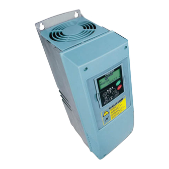
Vacon NX series Operating Manual
Dc/dc converter
Hide thumbs
Also See for NX series:
- Applications manual (392 pages) ,
- User manual (122 pages) ,
- Maintenance manual (65 pages)
Table of Contents
Advertisement
Quick Links
Advertisement
Table of Contents

Summary of Contents for Vacon NX series
- Page 1 ® ac drives dc/dc converter operating guide...
-
Page 3: Table Of Contents
• 1 TABLE OF CONTENTS Document ID:DPD01901A Revision release date: 01.11.2016 1. Introduction ........................ 2 Application functionality......................2 Connection..........................2 2. Parameters ......................... 7 Source side parameters......................7 2.1.1 Basic parameters....................7 2.1.2 Voltage reference....................8 2.1.3 Current reference ....................9 2.1.4... -
Page 4: Introduction
• 2 Introduction NTRODUCTION The DC/DC application creates output according to the needs of the system, and it is possible to integrate into the system with different topologies. Choosing applicable topology, see the Design Guide, Hybridization (DPD01887A). Application functionality... - Page 5 Introduction vacon • 3 B+/R+ U V W L1 L2 L3 U V W L1 L2 L3 U V W L1 L2 L3 U/T1 V/T2 W/T3 U V W U V W L1 L2 L3 L1 L2 L3 B+/R+ Figure 2. FR4-FR9 main terminals...
- Page 6 • 4 Introduction Figure 3. CH62 main terminals Local contacts: http://drives.danfoss.com/danfoss-drives/local-contacts/...
- Page 7 Introduction vacon • 5 DC+ DC- DC+ DC- FI 9/10 CONTROL H1..H7 U V W U V W FI4-FI8 FI9-FI10 Figure 4. FI4-FI10 basic wiring diagrams NOTE: The location and selection of fuses varies according to system design. Local contacts: http://drives.danfoss.com/danfoss-drives/local-contacts/...
- Page 8 • 6 Introduction DC+ DC- DC+ DC- FI10 FI10 CONTROL CONTROL X10 H1-H7 X10 H1-H7 U V W U V W FI10 FI10 Module 1 Module2 Figure 5. 2 x FI10 basic wiring diagram NOTE: The location and selection of fuses varies according to system design.
-
Page 9: Parameters
DC power source. There should also not be any load on the DC-link. Select the identification run and give the DC/DC converter a start command within 20 seconds after the identification mode is selected. 24-hour support +358 (0)201 212 575 • Email: service@vacon.com... -
Page 10: Voltage Reference
• 8 Parameters 2.1.2 Voltage reference Table 2. Voltage reference handling Code Parameter Unit Default Note P2.2.1.1 Voltage Reference 1462 P 2.2.1.2 Drooping Voltage Reference P 2.2.1.3 1867 Ramp Rate 0 = Reference Voltage Reference At 1 = Start Voltage Reference P2.2.1.4... -
Page 11: Current Reference
The U phase current reference on an individual mode. P2.2.2.2.3 IV C ID129 URRENT REFERENCE The V phase current reference on an individual mode. P2.2.2.2.4 IW C ID130 URRENT REFERENCE The W phase current reference on an individual mode. 24-hour support +358 (0)201 212 575 • Email: service@vacon.com... -
Page 12: Source Voltage
• 10 Parameters 2.1.4 Source voltage Table 4. Source voltage Code Parameter Unit Default Note P2.5.4.1 Source min voltage 50.0 1100.0 200/345 1893 Discharge limit P2.5.4.2 Source max voltage 50.0 1100.0 749/1099 1895 Charge limit Source voltage P2.5.4.3 100.0... -
Page 13: Dc-Link Side Parameters
NDER VOLTAGE DROOP The under voltage reference drooping. The set drooping is reached when the active current is 100%. NOTE: For more detailed parameter information, see the Vacon NX Programming Guide (DPD01886A). 24-hour support +358 (0)201 212 575 • Email: service@vacon.com... -
Page 14: Control Io
• 12 Control IO ONTROL Table 8. Default I/O configuration NXOPTA1 Terminal Signal Description Voltege for +10 Vref Reference voltege output potentiometer, etc. Analogue input 1. Analogue input 1Input range Range 0-10V, R = 200 Ω AI1+ selected by jumpers. - Page 15 Document ID: *DPD01901A* Vacon Ltd DPD01901A Member of the Danfoss Group Rev. A Runsorintie 7 65380 Vaasa Sales code: DOC-INSDCDC+DLUK Finland...


Need help?
Do you have a question about the NX series and is the answer not in the manual?
Questions and answers