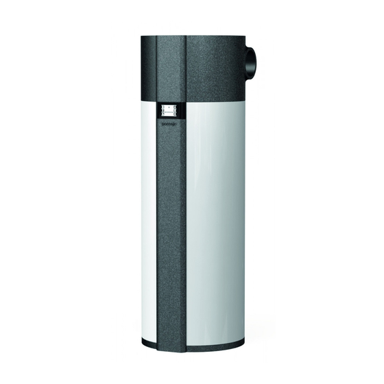
Gorenje TC 200 Instructions For Use Manual
Hide thumbs
Also See for TC 200:
- Instructions for use manual (40 pages) ,
- Instructions for use manual (56 pages) ,
- Instructions for use manual (40 pages)
Table of Contents
Advertisement
Available languages
Available languages
Quick Links
Advertisement
Table of Contents

Related Manuals for Gorenje TC 200


Summary of Contents for Gorenje TC 200
- Page 1 TC 200 - 300 NAVODILO ZA UPORABO INSTRUCTIONS FOR USE www.gorenje.com...
- Page 2 OPOZORILA Aparat lahko uporabljajo otroci stari 8 let in starejši in osebe z zmanjšanimi fizičnimi, čutnimi ali mentalnimi sposobnostmi ali s pomanjkanjem izkušenj oz. znanjem če so pod nadzorom ali poučeni glede uporabe aparata na varen način in da razumejo možne nevarnosti. Otroci se ne smejo igrati z aparatom.
-
Page 3: Področje Uporabe
To knjižico shranite, da jo boste lahko pogledali, kadar boste v dvomih glede delovanja ali vzdrževanja. Navodila za namestitev in uporabo so prav tako na voljo na naših spletnih straneh http://www.gorenje.com ali na nacionalnih straneh v rubriki servis oziroma podpora. - Page 4 Y = Nizkotemperaturno delovanje NT – če ni oznake ga ni X = Vgrajeno grelo G – če ni oznake ga ni Toplotna črpalka s integralnim agregatom in enim izmenjevalcem Tipi TC 200 Z XY TC 201 Z XY TC 300 Z XY TC 301 Z XY...
- Page 5 VM Vstop medija PT (črna rozeta) TV Odtok tople vode (rdeča rozeta) Cev za tipalo Cev za tipalo VZ Vstop zraka Izstop zraka TC 200 ZG TC 201 ZG TC 300 ZG TC 301 ZG TC 302 ZG A (mm)
- Page 6 NAMESTITEV HRANILNIKA TOPLE VODE S TOPLOTNO ČRPALKO Hranilnik tople vode s toplotno črpalko je možno uporabiti pri obratovanju s prostorskim ali vodenim zrakom. Za preprečitev podtlaka v zgradbi morate v prostore nadzorovano dovajati svež zrak. Željena stopnja izmenjave zraka za stanovanjsko zgradbo znaša 0,5.
- Page 7 DOLOČITEV PADCEV TLAKA PRI CEVOVODNEM SISTEMU DOVAJANJA IN ODVAJANJA ZRAKA Toplotna črpalka omogoča različne namestitve cevnih priklopov sesalnega in izpušnega zraka. Priporočljivo je uporabiti tiste priklope, ki omogočajo najenostavnejšo priključitev aparata na kanalski sistem. Pri samem načrtovanju cevovodnega sistema za dovajanje in odvajanje zraka, v oz.
- Page 8 Vrednosti skupnega padca statičnega tlaka se izračunajo s seštevanjem izgub posameznega elementa vgrajenega v zračnem cevovodnem sistemu. Vrednosti padcev statičnega tlaka posameznega elementa (padci statičnega tlaka elementov se nanašajo na notranji premer 150 mm) so prikazane v tabeli. Vrste elementov ter pripadajoče vrednosti padcev tlakov Vrednost padca Vrsta elementa statičnega tlaka...
- Page 9 Za zmanjšanje prenosa hrupa in tresljajev vgrajenega ventilatorja upoštevajte naslednje ukrepe, da se zvok delovanja in vibracije ne prenašajo preko sten v prostore, kjer bi bilo to moteče (spalnice, prostori za počitek): • vgradite fleksibilne povezave za hidravlične priključke • vgradite fleksibilno cev za cevovod odvodnega/dovodnega zraka •...
- Page 10 PRIKLJUČITEV NA DRUGE VIRE OGREVANJA Hranilnik tople vode s toplotno črpalko omogoča pripravo sanitarne vode preko enega ali dveh izmenjevalcev toplote z različnimi viri energije (npr. centralno ogrevanje, sončna energija, … ). Možnosti povezave hranilnika tople vode z različnimi viri ogrevanja so prikazane na skicah. Sl.
-
Page 11: Priključitev Na Električno Omrežje
PRIKLJUČITEV NA ELEKTRIČNO OMREŽJE Za priključitev hranilnika tople vode s toplotno črpalko je potrebno zagotoviti vtičnico, ki je primerna za tokovno obremenitev 16A. Priključitev toplotne črpalke na električno omrežje mora potekati v skladu s standardi za električne napeljave. Med toplotno črpalko in trajno inštalacijo mora biti vgrajena priprava za ločitev vseh polov od električnega omrežja v skladu z nacionalnimi inštalacijskimi predpisi. - Page 12 Vklop / izklop toplotne črpalke • Za vklop toplotne črpalke pritisnite na polje 9. Pri zagonu aparata se najprej vklopi ventilator, ta deluje 1 minuto (prikazan je simbol 20). Če je temperatura vstopnega zraka primerna, krmilnik vklopi še kompresor in toplotna črpalka deluje v normalnem režimu (prikazana sta simbola 16 in 20). Toplotna črpalka je vklopljena, zaslon je neosvetljen.
-
Page 13: Nastavitev Temperature
15 - Vklop načina delovanja "HOT" 5 - Nastavitev 13 - Vklop načina delovanja "TURBO" temperature Sl. 11: Nastavitev temperature, vklop načina "TURBO" in "HOT" Nastavitev temperature • Pritisnite na polje 5 (prikaže se utripajoče nastavljena temperatura). • S pritiskom na polje + ali – spreminjate nastavitev temperature od 10 do 75 °C oz. 10 do 65°C (modeli Z) tovarniška nastavitev je ekonomična temperatura 55 °C. - Page 14 Nastavitev časovnega načina delovanja V časovnem načinu delovanja nastavite čas vklopov in izklopov gretja vode. Za vsako kombinacijo časovnega obdobja je možno nastaviti do tri časovne periode v katerih toplotna črpalka ne bo segrevala vode. a) Nastavitev časovnih period • Za dalj časa pritisnite na polje 11 (polji 7 in 11 pričneta utripati). •...
- Page 15 Dostop do servisnega nivoja • Z daljšim pritiskom na polje 4 na prikazovalniku Sl. 10, se vklopi funkcija »servisni režim«. • Pojavi se vstopni meni z napisom code v polju CLOCK, za vnos servisne kode (polja FN1, FN2, FN3, FN4, FN5 in FN6), predstavljajo števila 1, 2, 3, 4, 5, 6 za vnos kode.
- Page 16 Prezračevanje • Vklop funkcije je mogoč s kratkim pritiskom na polje 2. Funkcija se avtomatsko izklopi po 30 minutah delovanja. • V primeru ponovnega kratkega pritiska se funkcija prezračevanje izključi. • V primeru izklopa toplotne črpalke s tipko on/off se funkcija izključi. •...
- Page 17 FUNKCIJA PV (PHOTOVOLTAIC) • V primeru sklenjenega breznapetostnega kontakta med sponkama 1 in 2 je PV funkcija aktivna (slika. 17). • V primeru sklenjenega breznapetostnega kontakta med sponkama 1 in 2 je na zaslonu je prikazano polje 1. • Za sklenitev breznapetostnega kontakta je potrebno s fotovoltaiko zagotoviti 800W električne moči. •...
- Page 18 Priklop zaznavanja PV (photovoltaic) Povezavo PV modula na toplotno črpalko sme priključiti le za to usposobljen strokovnjak. Na zadnji strani toplotne črpalke, pod priključno vrvico, je pripravljena uvodnica za priključitev PV funkcije. Mesto uvodnice je prikazano na Sl. 16. Za priključitev uporabite priključno vrvico minimalnega preseka vodnikov vsaj 0,5 mm (H05VV-F 2G 0,5 mm ) in maksimalnim zunanjim presekom 10mm,...
-
Page 19: Motnje V Delovanju
• Kličite servis (avtomatski preklop na segrevanje z električnim grelcem). E363 • Napaka senzorja odtaljevanja. • Kličite servis (avtomatski preklop na segrevanje z električnim grelcem). PRIDRŽUJEMO SI PRAVICO DO SPREMEMB, KI NE VPLIVAJO NA FUNKCIONALNOST APARATA. Navodila za uporabo so na voljo tudi na naših spletnih straneh http://www.gorenje.com. - Page 20 WARNINGS! The appliance may be used by children aged 8 and older and persons with physical, sensory or mental disabilities or lacking experience or knowledge, if they are under supervision or taught about safe use of the appliance and if they are aware of the potential dangers.
-
Page 21: Storage And Transport
Store this booklet for times of doubt upon the functioning or maintenance. The installation manual is available on our webpage http://www.gorenje.com or the webpages per country in the service and support section. -
Page 22: Technical Characteristics
X = installed heater G – if there is no sign, there is no heater Heat pump with an integrated aggregate and one exchanger Type TC 200 Z XY TC 201 Z XY TC 300 Z XY TC 301 Z XY... - Page 23 VM Inlet PT (black rosette) TV Hot water outlet (T – red rosette) Sensor pipe Sensor pipe VZ Air inlet Air outlet TC 200 ZG TC 201 ZG TC 300 ZG TC 301 ZG TC 302 ZG A (mm) 1170...
- Page 24 INSTALLATION OF THE HOT WATER STORAGE TANK WITH THE HEAT PUMP The heat pump can be used using the ambient air or air from other premises. To prevent pressure depression in the building, fresh air must be regularly supplied to the premises. The desired rate of air exchange for a residential building is 0.5.
- Page 25 DETERMINING PRESSURE LOSS IN THE AIR INLET AND OUTLET PIPELINE SYSTEM The heat pump offers various installation options of connection of the air inlet and outlet pipelines. We recommend the connection options, which enable the simplest installation of the appliance to the pipeline system. When designing the pipeline system for air inlet and outlet to and from the heat pump it is essential to consider the aerodynamic characteristics of the heat pump fan, where the static pressure loss occurs.
- Page 26 Values of total static pressure drop are calculated by adding up pressure drops of each individual element, installed in the air pipeline system. Values of pressure drops of each individual element (diameter 150 mm) are presented in the following table. Element types and their pressure drops.
- Page 27 To reduce noise and vibrations of the installed fan take the following steps to prevent the noise and vibrations to be transmitted through walls into rooms, where it would be disturbing (bedrooms, restrooms): • install flexible connectors for hydraulic jacks •...
- Page 28 CONNECTION TO OTHER HEATING SOURCES Hot water storage tank with the heat pump enables water heating via one or two heat exchangers with different energy sources (e.g. central heating, solar energy ...). Connection options to different heating sources are shown below. Figure 8: Connecting to other heating sources With a temperature decline of an additional heating source and with an enabled water circulation through the heat exchanger proper temperature control of the additional source must be ensured.
-
Page 29: Heat Pump Operation
CONNECTION TO THE POWER SUPPLY NETWORK In order to connect the hot water storage tank with the heat pump to the power supply network first install an electrical socket suitable for the current load of 16 A. Connecting the heat pump to the power supply network must take place in accordance with the standards for electric appliances. To comply with the national installation regulations, an all poles disconnect switch must be installed between the heat pump and the power supply network. -
Page 30: Power Failure Protection
Starting/stopping the heat pump • To start the heat pump, hold field no. 9. When the appliance is switched on, the fan starts first and operates for one minute (symbol no. 20 is displayed). If the temperature of inlet air is appropriate, the controlling unit switches on the compressor and the heat pump operates in normal mode (symbols 16 and 20 are displayed). -
Page 31: Setting The Temperature
15 - Switch on “HOT” mode 5 - Temperature 13 - Switch on “TURBO” mode settings Figure 11: Temperature settings, switch on “TURBO” and “HOT” mode Setting the temperature • Press field no. 5 (the set temperature starts blinking). • By pressing + or – you can change the temperature setting from 10 °C to 75 °C or 10 to 65 ° C (Z models), preset to economic temperature of 55 °C. - Page 32 Setting the TIMER mode In the TIMER operating mode, you can set the times when the heat pump will start and stop. For each timer combination you can set up to three time periods in which the heat pump will not heat the water. a) Setting the timer combinations •...
-
Page 33: Anti-Legionella Function
Maintenance level access • By pressing field no. 4, you can activate the maintenance mode (Figure 10). • A display menu with an inscription “code” in the filed CLOCK appears. Enter the maintenance code (fields FN1, FN2, FN3, FN4, FN5 in FN6 for numbers 1, 2, 3, 4, 5, 6). TEMP CLOCK MINUS... - Page 34 Ventilation • Activate ventilation by pressing field no. 2. The function is automatically switched off after 30 minutes. • By shortly pressing the filed 2 again, the ventilation is deactivated. • By shutting down the heat pump with the on/off options the ventilation is deactivated. •...
- Page 35 PV (PHPHOTOVOLTAICS) • In case of voltage free contact between clamps 1 and 2 PV is activated (Figure 17). • In case of voltage free contact between clamps 1 and 2 field 1 is displayed. • The voltage free contact requires 800 W of electrical power. •...
- Page 36 PV detection The connection of the PV module to the heat pump must be performed by a qualified expert. On the back side of the heat pump, under the connection cord, there is a PV connection port. The PV port is shown in figure 16. Use a connection cord (minimum inner cross-section 0,5 mm , H05VV-F 2G 0,5 mm and maximum external cross-section of 10 mm).
-
Page 37: Service And Maintenance
E363 • Defrosting sensor error. • Call the service (automatically switches to the electric heater). WE RESERVE THE RIGHT TO ANY MODIFICATIONS NOT AFFECTING THE FUNCTIONALITY OF THE APPLIANCE. The instructions for use are also available on our website http://www.gorenje.com. - Page 40 TC 200 - 300 05/2017 534995...
Need help?
Do you have a question about the TC 200 and is the answer not in the manual?
Questions and answers