Siemens SIMATIC ET 200SP Manual
Digital input module di 8xnamur
Hide thumbs
Also See for SIMATIC ET 200SP:
- System manual (409 pages) ,
- Manual (270 pages) ,
- Operating instructions manual (166 pages)

Related Manuals for Siemens SIMATIC ET 200SP


Summary of Contents for Siemens SIMATIC ET 200SP
- Page 1 SIMATIC ET 200SP Digital input module DI 8xNAMUR (6ES7131-6TF00-0CA0) Manual Edition 02/2014 Answers for industry.
-
Page 2: Manual, 02/2014, A5E03894478
___________________ DI 8xNAMUR HF digital input module Preface (6ES7131-6TF00-0CA0) ___________________ Guide to documentation ___________________ Product overview SIMATIC ___________________ Wiring ET 200SP ___________________ DI 8xNAMUR HF Parameters/address space digital input module ___________________ (6ES7131-6TF00-0CA0) Interrupts/diagnostics alarms Manual ___________________ Technical specifications ___________________ Parameter data record 02/2014 A5E03894478-01... - Page 3 Note the following: WARNING Siemens products may only be used for the applications described in the catalog and in the relevant technical documentation. If products and components from other manufacturers are used, these must be recommended or approved by Siemens. Proper transport, storage, installation, assembly, commissioning, operation and maintenance are required to ensure that the products operate safely and without any problems.
-
Page 4: Preface
Siemens recommends strongly that you regularly check for product updates. For the secure operation of Siemens products and solutions, it is necessary to take suitable preventive action (e.g. cell protection concept) and integrate each component into a holistic, state-of-the-art industrial security concept. -
Page 5: Table Of Contents
Table of contents Preface ..............................3 Guide to documentation .......................... 5 Product overview ............................ 7 Properties ............................7 Wiring ..............................9 Pin assignment ..........................9 Block diagram ..........................10 Parameters/address space ........................11 Parameters ..........................11 Explanation of parameters ......................13 Pulse stretching ........................... -
Page 6: Guide To Documentation
Documentation for the DI 8×NAMUR HF digital input module Topic Documentation Key contents System description System manual ET 200SP distributed Application planning • I/O system Installation • (http://support.automation.siemens.co Wiring • m/WW/view/en/58649293) Commissioning • Designing interference- Function manual Designing Basics • free controllers... - Page 7 Guide to documentation SIMATIC manuals All current manuals for SIMATIC products are available to download free of charge on the Internet (http://www.siemens.com/simatic-tech-doku-portal). DI 8xNAMUR HF digital input module (6ES7131-6TF00-0CA0) Manual, 02/2014, A5E03894478-01...
-
Page 8: Product Overview
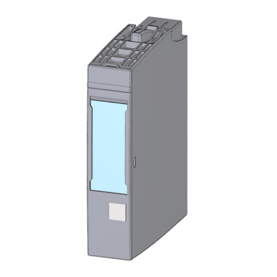
Product overview Properties Order number 6ES7131-6TF00-0CA0 View of the module Figure 2-1 View of the DI 8×NAMUR HF module DI 8xNAMUR HF digital input module (6ES7131-6TF00-0CA0) Manual, 02/2014, A5E03894478-01... - Page 9 ● Color identification labels ● Reference identification label ● Shield connection You can find additional information on the accessories in the ET 200SP distributed I/O system (http://support.automation.siemens.com/WW/view/en/58649293) system manual. See also ET 200SP Product information (http://support.automation.siemens.com/WW/view/en/73021864) DI 8xNAMUR HF digital input module (6ES7131-6TF00-0CA0)
-
Page 10: Wiring
Wiring Pin assignment General pin assignment Table 3- 1 Pin assignment for DI 8×NAMUR HF Pin assignment for DI 8×NAMUR HF (6ES7131-6TF00-0CA0) Terminal Assign- Terminal Assign- Description BaseUnit Color identification label ment ment (terminals 1 to 16) : Input signal, channel n •... -
Page 11: Block Diagram
When updating the firmware, the L+ supply voltage must be applied to the module at the start and during the firmware update. See also ET 200SP distributed I/O system (http://support.automation.siemens.com/WW/view/en/58649293) Block diagram Block diagram Figure 3-1 Block diagram DI 8×NAMUR HF... -
Page 12: Parameters/Address Space
Parameters/address space Parameters DI 8xNAMUR HF parameters The following table lists the configurable parameters. The effective range of the configurable parameters depends on the type of configuration. The following configurations are possible: ● Distributed operation on PROFINET IO in an ET 200SP system ●... - Page 13 Parameters/address space 4.1 Parameters Parameters Value range Default Changing Effective range with configuration parameter software, e.g. STEP 7 (TIA-Portal) settings in RUN GSD file GSD file PROFINET IO PROFIBUS DP Hardware interrupts • Deactivated Channel Deactivated Rising edge • Falling edge •...
-
Page 14: Explanation Of Parameters
Parameters/address space 4.2 Explanation of parameters Technology functions All technology functions, such as ● Pulse stretching ● Chatter monitoring ● Changeover errors ● Hardware interrupts are executed only when there is an error-free signal (QI = 1). In other words, there is no diagnostics information on the channel (see also section Address space (Page 18)). - Page 15 Parameters/address space 4.2 Explanation of parameters Diagnostics: Changeover error The diagnostics alarm is enabled when a changeover error occurs. "Changeover error" diagnostics is available with the following sensor setting: ● NAMUR changeover contact ● Changeover contact, unconnected ● Changeover contact with 10 kΩ Diagnostics: Chatter error The diagnostics alarm is enabled when a chatter error occurs.
- Page 16 ● Single contact with 10 kΩ Potential group Specifies that a BaseUnit with an incoming supply voltage is located in this slot (see ET 200SP distributed I/O system (http://support.automation.siemens.com/WW/view/en/58649293) system manual). See also Pin assignment (Page 9) Pulse stretching (Page 16)
-
Page 17: Pulse Stretching
Parameters/address space 4.3 Pulse stretching Pulse stretching Description Pulse stretching is a function for changing a digital input signal. A pulse at a digital input is extended to at least the configured length. If the input pulse is already longer than the configured length, then the pulse will not be changed. - Page 18 Parameters/address space 4.3 Pulse stretching Note If you set pulse stretching for an input channel, this will also affect the chatter monitoring that is enabled for this channel. The "pulse-stretched" signal is the input signal for the chatter monitoring. You should therefore match the parameter settings for pulse stretching and chatter monitoring to one another.
-
Page 19: Address Space
Parameters/address space 4.4 Address space Address space Configuration options of the DI 8×NAMUR HF Configuration with value status: ● DI 8×NAMUR HF QI Evaluating the value status As a result of configuration with value status (QI), an additional byte is allocated in the input address space. -
Page 20: Interrupts/Diagnostics Alarms
Interrupts/diagnostics alarms Status and fault displays LED displays The figure below shows the LED displays (status and fault displays) of the DI 8×NAMUR HF. ① DIAG (green/red) ② Channel status (green) ③ Channel fault (red) ④ PWR (green) Figure 5-1 LED display DI 8xNAMUR HF digital input module (6ES7131-6TF00-0CA0) Manual, 02/2014, A5E03894478-01... - Page 21 Interrupts/diagnostics alarms 5.1 Status and fault displays Meaning of the LEDs The tables below explain the meaning of the status and fault displays. Corrective measures for diagnostics alarms can be found in chapter Diagnostics alarms (Page 24). LED DIAG Table 5- 1 LED DIAG fault display LED DIAG Meaning...
- Page 22 Interrupts/diagnostics alarms 5.1 Status and fault displays LED PWR Table 5- 3 LED PWR status display LED PWR Meaning Supply voltage L+ is missing, is too low or polarity reversed Supply voltage L+ present DI 8xNAMUR HF digital input module (6ES7131-6TF00-0CA0) Manual, 02/2014, A5E03894478-01...
-
Page 23: Interrupts
Interrupts/diagnostics alarms 5.2 Interrupts Interrupts Digital input module DI 8×NAMUR HF supports the following diagnostics and hardware interrupts. Diagnostics interrupt The module generates a diagnostics interrupt at the following events: ● Short-circuit to ground ● Wire break ● Supply voltage missing ●... - Page 24 Interrupts/diagnostics alarms 5.2 Interrupts Structure of the additional interrupt information Table 5- 4 Structure of USI = W#16#0001 Data block name Contents Comment Bytes W#16#0001 Additional interrupt information for hardware interrupts of the I/O module (User Structure Identifier) The channel that triggered the hardware interrupt follows. Channel B#16#00 to B#16#07 Channel 0 to 7 of the I/O module...
-
Page 25: Diagnostics Alarms
Interrupts/diagnostics alarms 5.3 Diagnostics alarms Diagnostics alarms Diagnostics alarms A diagnostics alarm is output for each diagnostics event and the LED DIAG flashes on the module. Diagnostics alarms can, for example, be read from the diagnostics buffer of the CPU. You can evaluate the fault codes with the user program. Table 5- 5 Diagnostics alarms, meaning and corrective measures Diagnostics alarm... -
Page 26: Diagnostics For Changeover Contact Sensor Type
Interrupts/diagnostics alarms 5.4 Diagnostics for changeover contact sensor type Diagnostics for changeover contact sensor type Diagnostics for changeover contact sensor type With the changeover error diagnostics, the switchover between two input channels is checked. If there is a signal change in a changeover contact channel and there is no signal change at the other contact changeover channel after the tolerated switchover time, the diagnostics module returns a changeover error. -
Page 27: Chatter Monitoring
Interrupts/diagnostics alarms 5.5 Chatter monitoring Tip: Data records 0 to 7 and changeover sensor Using the data records 1, 3, 5 and 7, you can configure a changeover sensor on an even channel (normally closed contact channel). The corresponding normally open contact channel can be configured with the data records 0, 2, 4 and 6. - Page 28 Interrupts/diagnostics alarms 5.5 Chatter monitoring Reporting a chatter error If a chatter error occurs, the current signal status is entered in the process image and the value status of the signal is set to "invalid" (QI = 0). If "Chatter error" diagnostics is enabled, "Chatter error"...
- Page 29 Interrupts/diagnostics alarms 5.5 Chatter monitoring Chatter monitoring and "settling time" if a chatter error occurs Does the monitoring time in the event of a fault restart as three monitoring windows if the signal continues to change? The signal changes... Result once more often than set in the "Number of signal changes".
-
Page 30: Technical Specifications
Technical specifications Technical specifications DI 8×NAMUR HF technical specifications 6ES7131-6TF00-0CA0 Product type designation DI 8xNAMUR HF General information Usable BaseUnits BU type A0 Product function I&M data Yes; I&M0 to I&M3 Engineering with STEP 7 TIA Portal can be configured/integrated V13 / V13 as of version STEP 7 can be configured/integrated as of version V5.5 SP3 / V5.5 SP4... - Page 31 Technical specifications 6.1 Technical specifications 6ES7131-6TF00-0CA0 Input voltage Type of input voltage Rated value, DC 8.2 V Input current For 10 k connected contact 0.35 mA to 1.2 mA For signal "0" • 2.1 to 7 mA For signal "1" •...
- Page 32 NAMUR sensors and connected contacts Monitoring for short-circuit and wire break only for NAMUR sensors and connected contacts. The response ranges of the diagnostics correspond to IEC 60947-5-6. Dimension drawing See manual BaseUnits (http://support.automation.siemens.com/WW/view/en/58532597/133300) DI 8xNAMUR HF digital input module (6ES7131-6TF00-0CA0) Manual, 02/2014, A5E03894478-01...
-
Page 33: Parameter Data Record
Parameter data record Dependencies when configuring with GSD files When configuring the module with a GSD file, remember that the settings of some parameters are dependent on each other, see the tables below. Configuring with a PROFINET GSD file The table lists the diagnostics information and its dependencies on the sensor types for PROFINET. -
Page 34: Parameter Assignment And Structure Of Parameter Data Record
Parameter data record A.2 Parameter assignment and structure of parameter data record Parameter assignment and structure of parameter data record The data record 128 of the module has an identical structure, regardless of whether you configure the module with PROFIBUS DP or PROFINET IO. With data record 128, you can change the parameter assignment of the module in your user program regardless of its configuration. - Page 35 Parameter data record A.2 Parameter assignment and structure of parameter data record Structure of data record 128 and data records 0 to 7 Figure A-1 Structure of data record 128 and data records 0 to 7 Header information The figure below shows the structure of the header information. Figure A-2 DR 128 or DR 0 to 7: Bytes 0 and 1;...
- Page 36 Parameter data record A.2 Parameter assignment and structure of parameter data record Parameters The following figure shows the structure of the parameters for a channel. This structure also applies to channels 0 to 7. DI 8xNAMUR HF digital input module (6ES7131-6TF00-0CA0) Manual, 02/2014, A5E03894478-01...
- Page 37 Parameter data record A.2 Parameter assignment and structure of parameter data record Figure A-3 DR 128 or DR 0 to 7: Byte x to x+5: Structure for channels 0 to 7 See also Parameters (Page 11) DI 8xNAMUR HF digital input module (6ES7131-6TF00-0CA0) Manual, 02/2014, A5E03894478-01...
Need help?
Do you have a question about the SIMATIC ET 200SP and is the answer not in the manual?
Questions and answers