Table of Contents
Advertisement
Quick Links
9XCite-PKG-U™ USB RF Modem
9XCite USB RF Modem
RF Modem Operation
RF Modem Configuration
Advanced Networking
Appendices
Product Manual
For RF Modem Part Numbers: XC09-009PK...-U...
Low Power, Low Cost Boxed RF Modems by MaxStream, Inc.
MaxStream
355 South 520 West, Suite 180
Lindon, UT 84042
Phone: (801) 765-9885
Fax: (801) 765-9895
rf-xperts@maxstream.net
www.MaxStream.net (live chat support)
v2.1
XC09-038PK...-U...
M100180
2007.01.04
Advertisement
Table of Contents

Related Manuals for MaxStream 9XCite-PKG-U


Summary of Contents for MaxStream 9XCite-PKG-U
- Page 1 Advanced Networking Appendices Product Manual v2.1 For RF Modem Part Numbers: XC09-009PK…-U… XC09-038PK…-U… Low Power, Low Cost Boxed RF Modems by MaxStream, Inc. MaxStream 355 South 520 West, Suite 180 Lindon, UT 84042 Phone: (801) 765-9885 Fax: (801) 765-9895 rf-xperts@maxstream.net M100180 www.MaxStream.net (live chat support)
- Page 2 9XCite‐PKG‐U™ USB RF Modem ‐ Product Manual v2.1 [2007.01.04] © 2007 MaxStream, Inc. All rights reserved No part of the contents of this manual may be transmitted or reproduced in any form or by any means without the written permission of MaxStream, Inc. XCite™ and XCite‐PKG‐U™ are trademarks of MaxStream, Inc. Technical Support: Phone: (801) 765‐9885 Live Chat: www.maxstream.net E‐mail: rf‐xperts@maxstream.net © 2007 MaxStream, Inc. ii...
-
Page 3: Table Of Contents
2.1. Driver Installations 8 1-Year Warranty 34 2.1.1. USB Background Information 8 Ordering Information 34 2.2. System Description 9 Contact MaxStream 35 2.2.1. System Components 9 2.3. Modes of Operation 10 2.3.1. Idle Mode 10 2.3.2. Transmit Mode 10 2.3.3. Receive Mode 11 2.3.4. -
Page 4: Xcite Usb Rf Modem
Free & Unlimited Technical Support 1.1.1. Worldwide Acceptance FCC Certified (USA) [Refer to Appendix A for FCC Requirements] Systems that contain XCite Modems inherit MaxStream's FCC Certification IC (Industry Canada) Certified ISM (Industrial, Scientific & Medical) license-free 902-928 MHz frequency band Manufactured under ISO 9001:2000 registered standards © 2007 MaxStream, Inc. -
Page 5: Specifications
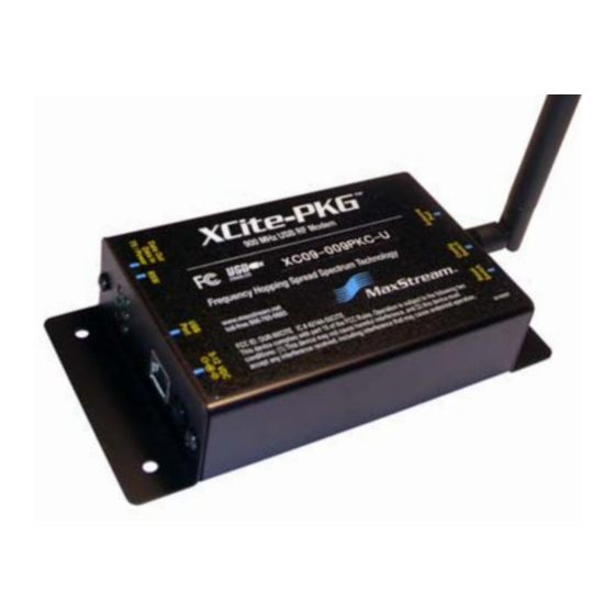
0 to 70º C (commercial) Antenna Connector RPSMA (Reverse-polarity SMA) Type Half-wave dipole whip, 6.75” (17.15cm), 2.1 dBi gain Impedance 50 ohms unbalanced Certifications (partial list) FCC Part 15.247 OUR-9XCITE Industry Canada (IC) 4214A-9XCITE 1.3. Mechanical Drawings Figure 1‐01. XCite‐PKG‐U (USB) RF Modem © 2007 MaxStream, Inc. -
Page 6: External Interface
Mode. To enter AT Command Mode at the RF modem's default Reset Switch Antenna Port baud rate, read the Reset Switch entry [above]. 1-03c. Antenna Port This port is a 50 Ohm RF signal connector for connecting to an RPSMA (Reverse Polarity SMA) type antenna. © 2007 MaxStream, Inc. -
Page 7: Pin Signals
The external power must supply a DC voltage between 5 and 12 V. The power supply currently shipped with MaxStream Development Kits is a suitable power supply for this option. XCite-PKG-U RF Modem automatically selects "self-powered mode" if power is available on the power connector when the RF modem is connected to USB. -
Page 8: Rf Modem Operation
USB has two types of devices: Those that supply drivers (a host, such as a PC); and those that require a driver (a client, such as a MaxStream USB RF Modem). When a USB client is plugged into a host, the host prompts for a driver. Once a driver is located, the host loads the driver on the first use of the USB client;... -
Page 9: System Description
The XCite-PKG-U USB RF Modem is most commonly used as an access point in a network of serial RF modems (such as MaxStream's RS-232/485 RF Modems). The XCite RF Modems support point- to-point, peer-to-peer, point-to-multipoint and multidrop network topologies. The section below illustrates a typical point-to-multipoint network application. -
Page 10: Modes Of Operation
After the channel is initialized, data in the DI buffer is grouped into packets (up to 64 bytes in each packet) and is transmitted. The modem continues to transmit data packets until the DI buffer is empty. Once transmission is finished, the modem returns to Idle Mode. This progression is shown below: Figure 2‐03. Transmission of data © 2007 MaxStream, Inc. 10... -
Page 11: Receive Mode
If serial data-to-transmit is stored in the DI buffer while the modem is giving precedence to Receive Mode, the data will be transmitted after the modem finishes receiving data and returns to Idle Mode. © 2007 MaxStream, Inc. 11... -
Page 12: Sleep Modes
When the modem awakens to listen for data, CTS is asserted and any data received on the DI Pin is transmitted. The PWR pin is also de-asserted (low) when the modem is in Cyclic Sleep Mode. These pins are asserted each time the modem cycles © 2007 MaxStream, Inc. 12... - Page 13 The cyclic interval time defined by the SM (Sleep Mode) command must be shorter than the interval time defined by LH (Wake-up Initializer Timer) command. Figure 2‐05. Correct Configuration (LH > SM): The length of the wake‐up initializer exceeds the time interval of Cyclic Sleep. The receiver is guaranteed to detect the wake‐up initializer and receive the accompanying payload data. © 2007 MaxStream, Inc. 13...
-
Page 14: Command Mode
Timeout) Command, the modem automatically returns to Idle Mode. [OR] Send ATCN (Exit Command Mode) Command. For an example of programming the RF modem using AT Commands and descriptions of each config- urable parameter, refer to the "RF Modem Configuration" chapter. © 2007 MaxStream, Inc. 14... -
Page 15: Rf Modem Configuration
• 900 MHz, 38400 Baud, Single Channel mode XCite Modems can operate in both Single Channel and Hopping modes. Mode is selectable using the "Function Set" dropdown list of the "XCite Configuration" tab of the MaxStream-provided X- CTU Software. The XCite Module is shipped with a unique parameter set in its memory. Parameters within the set are organized under the following categories: AT Commands &... -
Page 16: Configuration Software
A shortcut for editing PC Setting values is available by clicking on any of the values. Installation Double-click the "setup_X-CTU.exe" file and follow prompts of the installation screens. This file is located in the 'software' folder of the MaxStream CD and also under the 'Downloads' section of the following web page: www.maxstream.net/support/downloads.php Setup To use the X-CTU software, a module assembly (An RF modem mounted to an interface Board) must be connected to a serial port of a PC. -
Page 17: Command Reference Tables
[Read-only] Firmware Version. Read firmware version currently loaded on 0 – 0xFFFF Diagnostic radio modem. [Read-only] Write. Write parameters to radio modem’s non-volatile memory in order for changes to persist through next power-up (Special) or reset. © 2007 MaxStream, Inc. 17... - Page 18 Time before Sleep. Set time period of inactivity (no serial or RF data is sent or received) before activating Sleep Mode. 0x10 – 0xFFFF Sleep 0x64 Use with Cyclic Sleep and Serial Port Sleep [refer to SM [x 100 ms] (Low Power) (100d) Command] © 2007 MaxStream, Inc. 18...
-
Page 19: Command Descriptions
7 bits Setting 7 bits and Mark or Space parity (NB Parameter) will result in a setting of 7 bits and no 8 bits parity. Default Parameter Value: 1 Number of bytes returned: 1 © 2007 MaxStream, Inc. 19... - Page 20 Number of bytes returned: 1 CN (Exit AT Command Mode) Command <AT Command: AT Command Mode Options> CN Command allows users to explicitly exit AT Com- mand Mode and return the radio modem into Idle Mode. AT Command: CN © 2007 MaxStream, Inc. 20...
- Page 21 AT Command: DT Parameter Range: 0 - 0xFFFF # of bytes returned: 2 Default Parameter Value: 0 Related Commands: ID (Modem ID), HP (Channel), MK (Address Mask) © 2007 MaxStream, Inc. 21...
- Page 22 If Default Parameter Value: 0 channels used on different radio modems can be Number of bytes returned: 1 separated more they should be. This will provide for more isolation and less interference. © 2007 MaxStream, Inc. 22...
- Page 23 ID (Modem VID) Parameter <Non-AT Settable Parameter: Networking> ID Parameter reads and edits the modem's VID. VID is a MaxStream-specific acronym that stands for "Vendor Identification Number". RF modems can only communicate with other modems having the same VID. Parameter Range: 0 - 0x7FFF (above this range is Read-only)
- Page 24 Figure 3‐02. Incorrect Configuration (LH < SM) The length of the wake-up initializer is shorter than the time interval of Cyclic Sleep. This configu- ration is vulnerable to the receiver waking and missing the wake-up initializer (and therefore also the accompanying payload data). © 2007 MaxStream, Inc. 24...
- Page 25 However, RE Command will not write the default values to non-volatile mem- ory. Unless the WR (Write) Command is issued after the RE Command, the default settings will not be saved in the event of radio modem reset or power-down. AT Command: RE Related Command: WR (Write) © 2007 MaxStream, Inc. 25...
- Page 26 SL (Serial Number Low) Command <AT Command: AT Command Options> SL Command reads and reports the RF modem serial number low word. AT Command: SL Parameter Range: 0 - 0xFFFF [Read-only] # of bytes returned: 2 Related Command: SH (Serial Number High) © 2007 MaxStream, Inc. 26...
- Page 27 <AT Command: (Special)> WR Command writes all configurable parameters to non-volatile mem- ory. Using WR Command saves parameters to the radio modem's persistent memory. (This means that the parameters remain in the radio modem's memory until explicitly overwritten by future uses of WR Command.) AT Command: WR © 2007 MaxStream, Inc. 27...
-
Page 28: Advanced Networking
Only modems with matching VIDs can communicate with each other. VID addressing ensures that radio modems ignore transmissions and receptions of XCite Radio Modems having a different VID in the same vicinity. To request a unique VID, contact MaxStream to obtain the VID Request Form. -
Page 29: Channel (Athp)
Refer to the “Bit-wise AND Truth” table for the Pseudo 'C' Code that qualifies the Destination Addresses and address masks. The Pseudo Code uses the bit-wise "AND" operation, "&". This operation is performed bit by bit on each of the 16 bits in the TXDT, RXDT and RXMK parameters. © 2007 MaxStream, Inc. 29... - Page 30 Destination Address of the Receiver, or if it matches the Receiver Address Mask, the packet is accepted. Otherwise, the packet is discarded. Note:When performing this comparison, any "0" values in the Receiver Address Mask are treated as irrelevant and are ignored. © 2007 MaxStream, Inc. 30...
-
Page 31: Appendix A: Agency Certifications
The XCite USB RF Modem complies with Part 15 of the FCC rules and regulations. Compliance with the labeling requirements, FCC notices and antenna usage guidelines is required. In order to operate under MaxStream’s FCC Certification, OEMs/integrators must comply with the following regulations: The OEM/integrator must ensure that the text provided with this device [Figure A-01] is placed on the outside of the final product and within the final product operation manual. -
Page 32: Limited Modular Approval
Section 15.203 (unique antenna connectors) and Section 15.247 (emissions). Fixed Base Station and Mobile Applications MaxStream RF Modems are pre-FCC approved for use in fixed base station and mobile applica- tions. When the antenna is mounted at least 20cm (8") from nearby persons, the application is considered a mobile application. -
Page 33: Ic (Industry Canada) Certification
900 MHz Radio Modems (including "Mag Mount", "Dome", "Multi-path" and "Panel" antennas). Because of the large number of approved antennas, MaxStream requests that you send specific information about an antenna you would like to use with the modem and MaxStream will evaluate whether the antenna is covered under our FCC filing. -
Page 34: Appendix B: Additional Information
1-year from the date of purchase. In the event of a product failure due to materials or workmanship, MaxStream will repair or replace the defec- tive product. For warranty service, return the defective product to MaxStream, shipping prepaid, for prompt repair or replacement. -
Page 35: Contact Maxstream
9XCite‐PKG‐U™ USB RF Modem – Product Manual v2.1 [2007.01.04] Contact MaxStream Free and unlimited technical support is included with every MaxStream Radio Modem sold. For the best in wireless data solutions and support, please use the following resources: Documentation: www.maxstream.net/support/downloads.php Technical Support: Phone. (866) 765-9885 toll-free U.S.A. & Canada (801) 765-9885 Worldwide Live Chat.
Need help?
Do you have a question about the 9XCite-PKG-U and is the answer not in the manual?
Questions and answers