
Related Manuals for Burkert 8081


Summary of Contents for Burkert 8081
-
Page 1: Operating Instructions
Type 8081 Water flow rate transmitter Wasser-Durchfluss-Transmitter Transmetteur de débit d’eau Operating Instructions Bedienungsanleitung Manuel utilisateur... - Page 2 We reserve the right to make technical changes without notice. Technische Änderungen vorbehalten. Sous réserve de modifications techniques. © 2008 Bürkert S.A.S Operating Instructions Jul2009/1_EU-ML_00560456...
-
Page 5: Table Of Contents
Type 8081 Water flow rate transmitter type 8081 Contents: About this mAnuAl .................5 technicAl dAtA ..................12 1.1. symbols used ..................5 6.1. conditions of use ................12 intended use ....................6 6.2. conformity to standards and directives ....... 12 2.1. - Page 6 ..................................23 10.1. safety instructions ................23 10.2. Adjustment of the 8081 ..............23 mAintenAnce ................... 23 11.1.
-
Page 7: About This Manual
Type 8081 Aboutthismanual AbouT This mAnuAl caution This manual describes the entire life cycle of the device. Please keep Warns you against a possible risk. this manual in a safe place, accessible to all users and any new own- • Failure to observe this warning can result in substantial or minor ers. injuries. this manual contains important safety information. notice Failure to comply with these instructions can lead to hazardous situations. Warns you against material damage. -
Page 8: Intended Use
Type 8081 intendeduse inTended use 2.1. Restraints Observe any existing restraints when the device is exported. use of the ultrasonic flow rate transmitter that does not com- ply with the instructions could present risks to people, nearby installations and the environment. 2.2. Foreseeable misuse • The 8081 transmitter is intended solely for the measurement of the flow rate in water or neutral liquids. •... -
Page 9: Basic Safety Information
Type 8081 Basicsafetyinformation bAsic sAFeTy inFoRmATion notice This safety information does not take into account: elements / components sensitive to electrostatic discharges • This device contains electronic components sensitive to electro- • any contingencies or occurences that may arise during assembly, static discharges. They can get damaged if they are touched by use and maintenance of the devices. an electrostatically charged person or object. In the worst case • the local safety regulations that the operator must ensure the staff scenario, these components are instantly destroyed or go out of in charge of assembly observe. order as soon as they are activated. • To minimise or even avoid all damage due to an electrostatic dis- charge, take all the precautions described in the EN 100 015-1 norm. danger due to high pressure. • Also ensure that you do not touch any of the live electrical com- danger due to high temperatures of the fluid. -
Page 10: General Information
Type 8081 Generalinformation GeneRAl inFoRmATion The legal warranty only covers possible defects in the 8081 flow rate sensor and its components. Bürkert cannot be held responsible for any losses or damage 4.1. contents of the delivery related to the product, the service, this warranty or other, When you receive the merchandise, make sure that the contents of including financial or intangible losses, the price paid for the the delivery have not been damaged in any way and ensure that they product, a loss of profits, revenues, data, enjoyment or use of correspond exactly with the delivery note or packing list. the product or of any related product, or indirect or fortuitous If this is not the case, contact us immediately. loss or damage. In the event of differences in interpretation and understanding of this paragraph 4.2, the French version alone shall prevail. The addresses of our international branches can be found on the last pages of this manual. Also on the internet, at: www.burkert.com Bürkert Company Locations 4.3. -
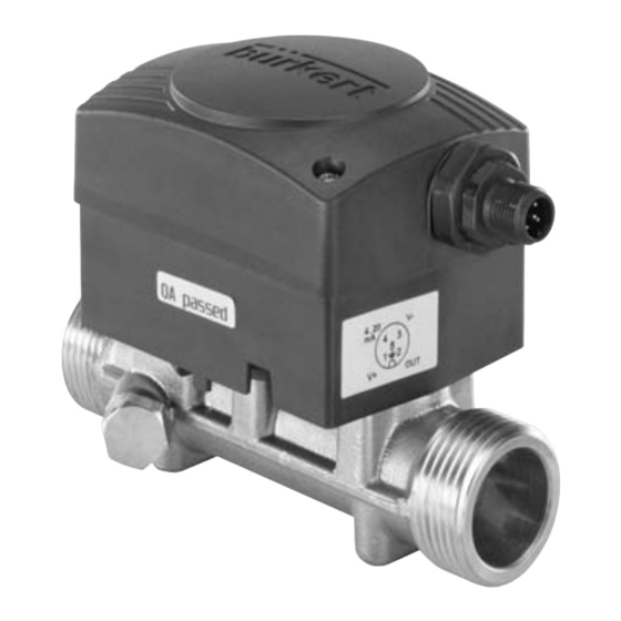
Page 11: Description
Type 8081 Description descRipTion • model QN 3.5 DN25: 0.6 to 116 l/min (nominal flow rate 3.5 m /h namely 58 l/min) • model QN 6 DN25: 1 to 200 l/min 5.1. Area of application (nominal flow rate 6 m /h namely 100 l/min) The ultrasonic flow rate transmitter type 8081 is intended for the measurement of water flow rates which may be slightly charged with 5.2.2. measuring item and principle contaminants. The 8081 flow meter is based on the transit time method. This con- sists in measuring the transit times of the sound from emitter 1 to 5.2. General description receiver 2 and from emitter 2 to receiver 1 and subsequently com- paring both values. The calculated transist time difference is directly 5.2.1. design proportional to the flow speed of the fluid. The 8081 ultrasonic flow rate transmitter consists of an electronic emitter-receiver emitter-receiver module and a brass fitting with a built-in measuring tube. When ultrasonic combined with a controller and a control loop, it enables a control wave 1 loop to be established. -
Page 12: Description Of The Label
Type 8081 Description the flow rate or to the temperature. 5.3. description of the label FLOW8081 ULTRASON DN20 NPN/PNP : 0,7A - 36VDC Measured quantity, type of flow meter 12-36 VDC 4-20mA MSEPDMFKM 0,16-82L/MIN Supply voltage S/N 1000 Measuring principle 00559869 W41LP Pipe diameter Output data Process connection Flow rate range Manufacturer's code Serial number 10. Order code 11. Materials: housing, seal english... -
Page 13: Order Codes
Type 8081 Description 5.4. order codes Pulse, NPN 559866 G 1'' external Pulse, NPN 560131 Pulse, PNP + thread G 3/4'' exter- 4-20 mA, sourcing 559869 Pulse, PNP + nal thread 0,16 to mode 2,5 20 4-20 mA, sourcing 560113 82 l/min 0.06 to mode Pulse, NPN 560614 0,6 15 20 l/min NPT 1'' exter- Pulse, NPN 560612 Pulse, PNP + nal thread NPT 3/4'' ex- 4-20 mA, sourcing 560619... -
Page 14: Technical Data
Type 8081 Technicaldata TechnicAl dATA 6.1. conditions of use Ambient temperature: +5 to +55 °C Storage temperature: +5 to +55 °C Pulse, NPN 560132 Air humidity: < 80%, not condensated G 1 1/4'' ex- Pulse, PNP + Protection rating: IP65 with cable plug plugged-in and ternal thread 4-20 mA, sourcing 560114 tightened 1 to mode 200 l/min 6.2. conformity to standards and Pulse, NPN 560616 NPT 1 1/4'' directives external Pulse, PNP + thread... -
Page 15: General Technical Data
Type 8081 Technicaldata 6.3. General technical data Dimensions [mm] 6.3.1. mechanical data item material Housing, cover Seal in contact with Silicone the environment M12 connector Brass Fitting Measuring tube Seal in contact with EPDM, FKM the fluid G or NPT 3/4'' 65.5 83.5 19.5 G or NPT 1'' 65.5 19.5 G or NPT 1 1/4'' 65.5 76.5 14.5 19.5 english... -
Page 16: General Data
Type 8081 Technicaldata 6.3.2. General data measurement accuracy Max. measurement max DN15 Pipe diameter DN15 to DN25 max DN20 deviation in % max DN25 Type of fluid water (or neutral liquids on request) Fluid temperature 5 to 90°C Fluid pressure PN 16 Measuring range 0.06 to 200 l/min 1000 Accuracy (see curves on ± (0.01 % of Full Scale* + 2% of next page) measured value) Flow rate in l/min Repeatability 1% of measured value Measuring element 2 ultrasound emitter-receiver cells * Full Scale, see measuring range on the diagram of measurement accuracy. -
Page 17: Electrical Characteristics
Type 8081 Technicaldata 6.3.3. electrical characteristics Current output 4-20 mA (sourcing mode as default set- ting; on request: sinking mode for the cur- 12-36 VDC Supply voltage (V+) rent output and NPN for the pulse output) corresponding to the flow rate range of Current consumption • Own consumption: < 4 mA the selected model (default setting) or to a temperature range (on request) • Consumption with load: < 1A max. loop resistance : Pulse output 1100 W at 36 V DC (transistor) 610 W at 24 V DC • version without • NPN as default setting; (PNP on 100 W at 12 V DC current output request), open collector, 5 mA min., Protection against: 700 mA max., NPN output: 0,2-36 VDC reversed polarity yes voltage peaks yes • version with cur- •... -
Page 18: Assembly
Type 8081 Assembly Assembly 7.2. Assembly of the 8081 notice 7.1. safety instructions When the cover is removed, the transmitter may be damaged through any element touching the electronics, and the tightness danger of the transmitter is no longer ensured. -
Page 19: Installation And Wiring
Type 8081 Installationandwiring insTAllATion And WiRinG Warning Risk of injury due to non-conforming installation. 8.1. safety instructions • The electrical and fluid installation can only be carried out by quali- fied and skilled staff with the appropriate tools danger • Install appropriate safety devices (correctly rated fuse and/or Risk of injury due to high pressure circuit-breaker). • Cut off the pressure and depressurize the pipes before loosening •... - Page 20 Type 8081 Installationandwiring The 8081 ultrasonic flow rate transmitter can be fitted onto a hori- It is advisable to avoid placing the 8081 transmitter near zontal or vertical pipe. any source of electromagnetic interference (switch, electric motor, fluorescent lamp, ...). When horizontally mounted, the max. fluid Minimum upstream and downstream distances are not necessary. Incorrect Correct temperature is 90°C. The 8081 works correctly when the pipe is full and free of any air But the max. fluid tem- bubbles near the transmitter. In presence of bubbles in the pipe, the perature must be re- left installation no.1 should be avoided. Incorrect duced to 80°C when the electronics (black enclo- sure) is turned upwards. When vertically mounted the max. fluid tempera- Correct ture is also 80°C. → Please be careful to respect the correct direction of fluid flow in the pipe. It is indicated with an arrow, marked on the If the absence of any air bubbles cannot be guaranteed, the device underside of the fitting.
-
Page 21: Electrical Wiring
Type 8081 Installationandwiring notice • The power supply must be filtered and regulated. When mounting the device on the pipe, the m12 fixed connector may be damaged. → Make sure the installation is earthed equipotentially If the M12 fixed connector is damaged the device cannot be used (power supply - 8081). anymore. → Connect the different earth connections of the installation to • Please be careful not to damage the M12 fixed connector when one another in order to remove any differences in potential mounting the device on the pipe. which may arise between the two earth connections. → Connect the cable shielding to the earth. Connect the nega- 8.3. electrical wiring tive terminal of the power supply to the earth to remove the effects of the common mode currents. If this connection can- danger... -
Page 22: Assembly Of The Female Cable Plug (Order Code 438680)
Type 8081 Installationandwiring 8.3.1. Assembly of the female cable plug 8.3.2. Wiring of the 5-pin m12 fixed (order code 438680) connector → Fully unscrew terminal 4-20 mA Not connected 0 VDC 0 VDC block [1] → Remove body [2]. → Unscrew clamping nut [5]. → Pass cables through Pulse output Pulse output clamping nut [5], then (12-30 VDC) -
Page 23: Connecting The Pulse Output
Type 8081 Installationandwiring 8.3.3. connecting the pulse output 8.3.4. only connecting the current output The pulse output is connected in NPN mode (default setting on a The current output, where present, is connected in source mode version without current output) or in PNP mode (default setting on a (default setting) or in sink mode (on request). version with current output). 4-20 mA 4-20 mA Load Load input input white white brown brown grey grey blue blue brown brown grey grey black 12-36 VDC... -
Page 24: Connecting Both The Current And Pulse Outputs
Type 8081 Commissioning 8.3.5. connecting both the current and commissioninG pulse outputs 9.1. safety instructions Load Load Warning danger due to non-conforming commissioning. Non-conforming commissioning could lead to injuries and damage white white the device and its surroundings. • Before commissioning, make sure that the staff in charge have brown brown read and fully understood the contents of the manual. -
Page 25: Adjustment And Functions
In particular, observe the safety recommendations and standard Risk of injury due to electrical discharge. operating practices. • Before starting work, be sure to switch off the supply voltage and • The device/installation must only be adjusted by suitably trained secure it to prevent restarting. staff. • Observe the applicable accident prevention and safety regulations for electrical equipment. 10.2. Adjustment of the 8081 Warning • Pulse output: The pulse output delivers a frequency in proportion to a volume. danger due to non-conforming maintenance. A pulse is generated each time a set volume passes, i.e. either • Maintenance must only be carried out by qualified and skilled staff V = 0.002 litre (for a model with QN = 0.6 or 1.5) or V = 0.005 li- with the appropriate tools. tre (for a model with QN = 2.5 or 3.5) or V = 0.01 li- • Following maintenance, ensure a controlled restart. -
Page 26: Cleaning
Type 8081 Packaging,transport 11.2. cleaning pAckAGinG, TRAnspoRT The 8081 flow meter can be cleaned with water or using a deter- notice gent compatible with the materials it is made of. damage due to transport Please feel free to contact your Bürkert supplier for any additional • Transport may damage an insufficiently protected device. information. • Transport the device in shock-resistant packaging and away from humidity and dirt. • Avoid the effects of heat and cold which could cause the storage temperature range to be exceeded. • Protect the electrical interfaces by using protection caps. english... -
Page 27: Storage
Type 8081 Storage sToRAGe disposAl oF The pRoducT → Dispose of the device and its packaging in an environmentally- notice friendly way. poor storage can damage the device. notice • Store the device in a dry place away from dust. • Storage temperature: +5 to +55°C. damage to the environment caused by products contaminated by fluids. - Page 28 Type 8081 Disposaloftheproduct english...
- Page 29 Type 8081 Disposaloftheproduct english...
- Page 30 Type 8081 Disposaloftheproduct english...
- Page 31 Typ 8081 Wasser-Durchfluss-Transmitter Typ 8081 5.4. Bestellnummer .................. 11 Inhaltsverzeichnis: technische Daten ................13 Die BeDienungsanleitung ...............5 6.1. Betriebsbedingungen ..............13 1.1. Darstellungsmittel ................5 6.2. normenbezüge und richtlinien ..........13 Bestimmungsgemässe VerwenDung ........6 6.3. allgemeine technische Daten ........... 13 2.1.
- Page 32 ................22 inBetrieBnahme ..................23 9.1. sicherheitshinweise ............... 23 BeDienung unD Funktion ............23 10.1. sicherheitshinweise ............... 23 10.2. Bedienung des 8081 ..............23 wartung ...................... 24 11.1. sicherheitshinweise ............... 24 11.2. reinigung ..................... 24 Verpackung, transport .............. 24 lagerung ....................
-
Page 33: Die Bedienungsanleitung
Typ 8081 DieBedienungsanleitung Die BeDienungsanleiTung VorsichT! Die Bedienungsanleitung beschreibt den gesamten Lebenszyklus warnt vor einer möglichen gefährdung! des Gerätes. Bewahren Sie diese Anleitung so auf, dass sie für jeden • Nichtbeachtung kann mittelschwere oder leichte Verletzungen Benutzer gut zugänglich ist und jedem neuen Eigentümer des Gerätes zur Folge haben. wieder zur Verfügung steht. hinWeis! Die Bedienungsanleitung enthält wichtige informationen zur warnt vor sachschäden! sicherheit! •... -
Page 34: Bestimmungsgemässe Verwendung
Typ 8081 BestimmungsgemässeVerwendung BesTimmungsgemässe 2.1. Beschränkungen VerwenDung Beachten Sie bei der Ausfuhr des Gerätes gegebenenfalls bestehende Beschränkungen. WarnunG 2.2. Vorhersehbarer Fehlgebrauch Bei nicht bestimmungsgemäßem einsatz des ultraschall-Durch- fluss-transmitters können gefahren für personen, anlagen in • Der Ultraschall-Durchfluss-Transmitter Typ 8081 darf nicht in explo- der umgebung und die umwelt entstehen. sionsgefährdeten Bereichen eingesetzt werden. • Der Transmitter 8081 darf nur zur Durchflussmessung von Wasser • Verwenden Sie keine Flüssigkeiten, die unvereinbar mit den Werk- oder neutralen Flüssigkeiten eingesetzt werden. -
Page 35: Grundlegende Sicherheitshinweise
Typ 8081 GrundlegendeSicherheitshinweise grunDlegenDe sicherheiTshinweise allgemeine gefahrensituationen Diese Sicherheitshinweise berücksichtigen keine Zum Schutz vor Verletzungen ist zu beachten • Zufälligkeiten und Ereignisse, die bei Montage, Betrieb und Wartung • Dass die Anlage nicht unbeabsichtigt betätigt werden kann. der Geräte auftreten können. • Installations- und Instandhaltungsarbeiten dürfen nur von auto- • ortsbezogenen Sicherheitsbestimmungen, für deren Einhaltung, risiertem Fachpersonal mit geeignetem Werkzeug ausgeführt auch in Bezug auf das Montagepersonal, der Betreiber verantwort- werden. lich ist. • Nach einer Unterbrechung der elektrischen Versorgung ist ein definierter oder kontrollierter Wiederanlauf des Prozesses zu gewährleisten... -
Page 36: Allgemeine Hinweise
Stand der Technik. Trotzdem Voraussetzung für die Gewährleistung ist der bestimmungsgemäße können Gefahren entstehen. Gebrauch des 8081 unter Beachtung der im vorliegenden Handbuch Bei Nichtbeachtung dieser Bedienungsanleitung und ihrer Hinwei- spezifizierten Einsatzbedingungen. Die Bedingungen für die eventuelle se sowie bei unzulässigen Eingriffen in das Gerät entfällt jegliche... -
Page 37: Informationen Im Internet
4.3. Informationen im Internet sich sehr einfach Durchfluss-Regelstrecken aufbauen. Der elektrische Anschluss erfolgt über einen M12-5Pin-Gerätestecker. Bedienungsanleitungen und Datenblätter zum Typ 8081 finden Sie Der Transmitter ist je nach Ausführung mit den folgenden Ausgän- im Internet unter: gen versehen: www.buerkert.de Dokumentation Datenblätter oder Bedienungs-... -
Page 38: Messelement Und Messprinzip
Typ 8081 Beschreibung • QN 3,5-Modell DN25 : 0,6 bis 116 l/min Das Elektronikmodul berechnet anhand der Laufzeitdifferenz die (Nenngröße 3,5 m /h d.h. 58,33 l/min) Fließgeschwindigkeit und stellt an dem Ausgang ein durchflusspro- portionales Frequenzsignal zur Verfügung. Weiterhin wird über ein • QN 6-Modell DN25 : 1 bis 200 l/min 4-20 mA Normsignal wahlweise der Durchfluss oder die Temperatur (Nenngröße 6 m /h d.h. 100 l/min) ausgegeben. 5.2.2. messelement und messprinzip 5.3. Beschreibung des Typenschilds Der Durchflussmesser 8081 verwendet die Ultraschall-Technologie Messgröße, Art des Durchflusssensors nach dem Laufzeit-Verfahren. Hierbei wird die Zeit gemessen, die Betriebsspannung der Schall von Sender 1 bis Empfänger 2 bzw. von Sender 2 bis Empfänger 1 benötigt. Die Differenz der beiden Laufzeiten ist direkt Messprinzip proportional zu der Fließgeschwindigkeit des Mediums. Nennweite Ausgang-Kenngrößen Sender-Empfänger Sender-Empfänger Prozessanschluss Durchflussbereich Ultraschall- Werkinterne Nummer... -
Page 39: Bestellnummer
Typ 8081 Beschreibung 5.4. Bestellnummer Durchfluss- leitungsan- Bestell- FLOW8081 ULTRASON DN20 Qn Dn ausgänge bereich schluss nummer NPN/PNP : 0,7A - 36VDC 12-36 VDC 4-20mA Puls, NPN 560131 MSEPDMFKM 0,16-82L/MIN Außengewinde S/N 1000 Puls, PNP + G 3/4'' 00559869 W41LP 4-20 mA im 560113 0,06 bis Quelle-Modus... - Page 40 Typ 8081 Beschreibung Durchfluss- leitungsan- Bestell- Durchfluss- leitungsan- Bestell- Qn Dn ausgänge Qn Dn ausgänge bereich schluss nummer bereich schluss nummer Puls, NPN 559866 Puls, NPN 560132 Außengewinde Außengewinde Puls, PNP + Puls, PNP + G 1'' G 1 1/4'' 4-20 mA im 559869 4-20 mA im 560114 0,16 bis Quelle-Modus 1 bis Quelle-Modus 2,5 20...
-
Page 41: Technische Daten
Typ 8081 TechnischeDaten Technische DaTen 6.3. allgemeine technische Daten 6.1. Betriebsbedingungen 6.3.1. mechanische Daten Umgebungstemperatur: 5 bis +55 °C teile werkstoff Lagerungstemperatur: 5 bis +55 °C Gehäuse, Deckel Luftfeuchtigkeit: < 80%, nicht kondensiert Dichtung mit der Umgebung Schutzklasse : IP65 mit eingesteckter und angezogener Silikon in Kontakt gesetzt M12-Steckdose M12-Stecker 6.2. normenbezüge und richtlinien Messing Fitting EMV: EN61000-6-3, 61000-6-2 Vibration: EN 60068-2-6 Messrohr Schock: EN 60068-2-27. -
Page 42: Allgemeine Daten
Typ 8081 TechnischeDaten abmessungen [mm] 6.3.2. allgemeine Daten Rohrdurchmesser DN15 bis DN25 Typ der Flüssigkeit Wasser (neutrale Flüssigkeit auf An- frage) Mediumstemperatur 5 bis 90 °C Mediumsdruck PN 16 Messbereich 0,06 bis 200 l/min Genauigkeit (siehe Dia- ± (0.01% vom Messbereichende* + gramm nächste Seite) 2% vom Messwert) Wiederholbarkeit 1% vom Messwert Messelement 2 Sender-Empfänger-Ultraschallzellen * Messbereichende, siehe Durchflussbereich auf Genauigkeitdiagramm Unter Referenzbedingungen, d.h. Messmedium = Wasser, Umgebungs- und Wassertemperatur = 20 °C,... -
Page 43: Elektrische Daten
Typ 8081 TechnischeDaten messgenauigkeit Diagramm 6.3.3. elektrische Daten 12-36 VDC max DN15 Versorgungs- max DN20 Max. Maßabweichung in % spannung (V+) max DN25 Stromaufnahme • Interne Stromaufnahme: < 4 mA • Stromaufnahme mit Last: < 1A Pulsausgang (Transistor) • Ausführung ohne • NPN als Grundeinstellung; (PNP Stromausgang auf Anfrage), Open Kollektor, 5 mA min., 700 mA max., NPN-Ausgang : 0,2-36 VDC 1000 • Ausführung mit • PNP als Grundeinstellung; (auf Anfrage: Stromausgang NPN für den Pulsausgang und Senke- Durchfluss in l/min Modus für den Stromausgang), Open... -
Page 44: Elektrischer Anschluss
Typ 8081 Montage monTage Schutz gegen : Falschpolung vorhanden Spannungsspitzen vorhanden 7.1. allgemeine sicherheitshinweise Kurzschluss vorhanden, für den Pulsausgang Gefahr! Stromausgang 4-20 mA (Quelle-Modus als Grundeinstel- lung; Auf Anfrage: Senke-Modus für den Verleztungsgefahr durch hohen Druck in der anlage! Stromausgang und NPN für den Pulsaus- • Vor dem Lösen von Leitungen und Fitting den Druck ablassen. gang) entspricht entweder dem Durch- flussbereich des ausgewählten Modells Verleztungsgefahr durch stromschlag! (Grundeinstellung) oder dem Temperatur- • Vor Eingriffen in die Anlage die Spannung abschalten und vor... -
Page 45: Montage Des 8081
Typ 8081 Installation 7.2. montage des 8081 insTallaTion hinWeis! 8.1. sicherheitshinweise wenn der Deckel entfernt ist, kann der transmitter durch kontakt zwischen dem element und der elektronik beschädigt werden und Gefahr! die Dichtheit ist dann auch nicht mehr gewährleistet. Verletzungsgefahr durch hohen Druck in der anlage! •... -
Page 46: Installation Auf Rohrleitung
Typ 8081 Installation Der Ultraschall-Durchfluss-Transmitter 8081 kann entweder in waa- WarnunG! gerechte oder senkrechte Rohre montiert werden. Verletzungsgefahr bei unsachgemäßer installation! Bei waagerechter Ein- • Fluidische und elektrische Installationen dürfen nur durch autori- baulage beträgt die max. Falsch Richtig siertes Fachpersonal und mit geeignetem Werkzeug durchgeführt Flüssigkeitstemperatur werden! 90 °C. • Es ist ratsam, Sicherheitsvorrichtungen für die Stromversorgung Die max. Flüssigkeitstem- Falsch zu installieren: richtig dimensionierte Sicherung und/oder Über- peratur verringert sich auf lastschalter. 80 °C, wenn die Elektro- • Nur Kabel mit einer für Ihren Prozess ausreichenden Temperatur- nik (schwarzes Gehäuse) beständigkeit verwenden. nach oben gedreht ist. • Bei normalen Betriebsbedingungen kann das Messsignal über... -
Page 47: Elektrische Installation
Typ 8081 Installation Wenn möglich ein Einbau des Transmitters 8081 in der hinWeis! Nähe Quellen von elektromagnetischen Störungen (Schal- Bei der montage des geräts auf die rohrleitung, kann der m12- ter, Elektromotor, Leuchtstofflampe, ...) vermeiden. stecker beschädigt werden. Mindesteinlauf- und Auslauf- Strecken müssen nicht eingehalten Wenn der M12-Stecker beschädigt ist, kann das Gerät nicht mehr werden. verwendet werden. Der Sensor 8081 gibt genaue Messungen, wenn das Rohr am • Beachten Sie die Integrität des M12-Steckers, bei der Montage Transmitter zu jedem Zeitpunkt vollständig gefüllt und frei von Luft- des Geräts auf die Rohrleitung. blasen ist. Mit Luftblasen im Rohr ist die Position 1 zu vermeiden. 8.3. elektrische installation Gefahr! Verletzungsgefahr durch stromschlag! • Vor Eingriffen in die Anlage die Spannung abschalten und vor Wiedereinschalten sichern! •... -
Page 48: Zusammenstellung Der M12- Steckdose (Bestell-Nr 438680)
Typ 8081 Installation 8.3.1. Zusammenstellung der m12- • Verwenden Sie eine gefilterte und geregelte Stromversor- steckdose (Bestell-nr 438680) gung. → Klemmleiste [1] aufschrau- → Stellen Sie die Äquipotentialität der Installation sicher (Strom- versorgung - 8081) → Gehäuse [2] entfernen. → Die verschiedenen Erdungspunkte der Installation aneinander → Klemmmutter [5] auf- anschließen, damit die zwischen zwei Erdungspunkten mögli- schrauben. cherweise erzeugten Potentialdifferenzen beseitigt werden. → → Kabel durch Klemmmutter Es muss auf vorschriftsmäßige Erdung der Abschirmung des [5] dann durch Klemmring Kabels geachtet werden. Erden Sie den negativen Anschluss der [4] und durch Dichtungs- Versorgungsquelle, um die Auswirkungen der Gleichtaktströme scheibe [3] und schließlich zu unterdrücken. Ist eine direkte Erdung unmöglich, schließen Sie durch Gehäuse [2] führen. einen 100 nF/50 V-Kondensator zwischen den negativen An- →... -
Page 49: Verkabelung Des M12-5Pin-Steckers
Typ 8081 Installation 8.3.2. Verkabelung des m12-5pin-steckers 8.3.3. anschluss des Pulsausgangs Der Pulsausgang kann entweder im NPN-(Grundeinstellung bei Nicht belegt 4-20 mA einer Ausführung ohne Stromausgang) oder PNP-(Grundeinstellung 0 VDC 0 VDC bei einer Ausführung mit Stromausgang) Modus angeschlossen werden. Pulsausgang Pulsausgang Last Last (12-30 VDC) (12-30 VDC) weiß weiß (NPN als Grund- (PNP als Grund- einstellung) einstellung) braun braun (*) Funktionelle Erde grau grau... -
Page 50: Anschluss Des Stromausgangs Allein
Typ 8081 Installation 8.3.4. anschluss des stromausgangs 8.3.5. anschluss des stromausgangs allein und des Pulsausgangs Der Stromausgang, wenn vorhanden, kann als Quelle (Grundeinstel- lung) oder als Senke (auf Anfrage) angeschlossen werden. Last Last 4-20 mA 4-20 mA Eingang Eingang weiß weiß braun braun braun braun grau grau schwarz blau blau blau blau Versorgung Versorgung 12-36 VDC... -
Page 51: Inbetriebnahme
Die Sicherheitshinweise und die bestimmungsgemäße Verwen- • Vor der Inbetriebnahme muss gewährleistet sein, dass der Inhalt dung müssen beachtet werden. der Bedienungsanleitung dem Bedienungspersonal bekannt ist und vollständig verstanden wurde. • Nur ausreichend geschultes Personal darf die Anlage/das Gerät bedienen. • Die Sicherheitshinweise und die bestimmungsgemäße Verwen- dung müssen beachtet werden. 10.2. Bedienung des 8081 • Nur ausreichend geschultes Personal darf die Anlage/das Gerät in Betrieb nehmen. • Pulsausgang: • Das Gerät muss vor elektromagnetischen Störungen, vor UV- Der Pulsausgang liefert eine Frequenz, welche proportional zu einer Bestrahlung und, bei Außenanwendung, vor Witterungseinflüssen Menge ist. geschützt werden. Für jeden Durchgang ist ein Puls eines der Ausführung entspre- chenden festgelegten Volumens der Flüssigkeit erzeugt, d.h. -
Page 52: Wartung
Typ 8081 Wartung warTung VerPackung, TransPorT hinWeis! 11.1. sicherheitshinweise transportschäden Gefahr Unzureichend geschützte Geräte können durch den Transport beschädigt werden. Verletzungsgefahr durch hohen Druck in der anlage! • Gerät vor Nässe und Schmutz geschützt in einer stoßfesten Ver- • Vor dem Lösen von Leitungen den Druck ablassen. packung transportieren. Verletzungsgefahr durch stromschlag! • Eine Über- bzw. Unterschreitung der zulässigen Lagertemperatur vermeiden. • Vor Eingriffen in die Anlage die Spannung abschalten und vor Wiedereinschalten sichern! •... -
Page 53: Lagerung
Typ 8081 Lagerung lagerung enTsorgung → Entsorgen Sie das Gerät und die Verpackung umweltgerecht. hinWeis! Falsche lagerung kann schäden am gerät verursachen. hinWeis! • Lagern Sie das Gerät trocken und staubfrei! umweltschäden durch von medien kontaminierte geräteteile. • Lagerungstemperatur: 5 bis +55 °C • Geltenden Entsorgungsvorschriften und Umweltbestimmungen einhalten. hinweis: Beachten Sie die nationalen Abfallbeseitigungsvorschriften. deutsch... - Page 54 Typ 8081 deutsch...
- Page 55 Typ 8081 deutsch...
- Page 56 Typ 8081 deutsch...
- Page 57 Type 8081 Transmetteur de débit d'eau Type 8081 Sommaire : A propos de ce mAnuel ..............5 cArActéristiques techniques ..........13 1.1. symboles utilisés ................5 6.1. conditions d'utilisation ..............13 utilisAtion conforme ................6 6.2. conformité aux normes et directives ........13 2.1.
- Page 58 ..................23 9.1. consignes de sécurité ..............23 réglAge et fonctionnAlités ............23 10.1. consignes de sécurité ..............23 10.2. réglage du 8081 ................23 mAintenAnce ................... 24 11.1. consignes de sécurité ..............24 11.2. entretien ....................24 embAllAge, trAnsport ..............
-
Page 59: A Propos De Ce Manuel
Type 8081 Aproposdecemanuel A propos de ce mAnuel aTTenTion Ce manuel décrit le cycle de vie complet de l'appareil. Conservez-le met en garde contre un risque éventuel. de sorte qu'il soit accessible à tout utilisateur et à disposition de tout •... -
Page 60: Utilisation Conforme
Le transmetteur 8081 est exclusivement destiné à la mesure du débit dans de l'eau ou des liquides neutres. • Le transmetteur de débit à ultrasons type 8081 ne doit pas être utilisé dans une atmosphère explosible. • Si possible, éviter de placer cet appareil à proximité de perturba- tions électromagnétiques,... -
Page 61: Consignes De Sécurité De Base
Type 8081 Consignesdesécuritédebase consignes de sécuriTé de bAse situations dangereuses diverses. Ces consignes de sécurité ne tiennent pas compte : Pour éviter toute blessure, veiller à : • des imprévus pouvant survenir lors du montage, de l'utilisation et de •... -
Page 62: Informations Générales
Type 8081 Informationsgénérales informATions générAles Le transmetteur de débit à ultrasons type 8081 a été dé- veloppé en intégrant les techniques de sécurité reconnues et est conforme à l'état de la technique. Tout danger n'est 4.1. contenu de la livraison cependant pas écarté. -
Page 63: Informations Sur Internet
Le transmetteur de débit à ultrasons type 8081 est destiné à la à cette garantie ou autre, y compris des pertes financières ou mesure du débit d'eau, pouvant être légèrement chargée. -
Page 64: É Lément Et Principe De Mesure
5.2.2. é lément et principe de mesure Grandeur mesurée, type de débitmètre Le débitmètre 8081 utilise la méthode de temps de transit. Celle-ci Tension d'alimentation consiste à mesurer les temps de propagation d'ondes ultrasonores Principe de mesure de l'émetteur 1 vers le récepteur 2 et de l'émetteur 2 vers le récep- Diamètre nominal... -
Page 65: Références De Commande
Type 8081 Description 5.4. références de commande FLOW8081 ULTRASON DN20 NPN/PNP : 0,7A - 36VDC 12-36 VDC 4-20mA MSEPDMFKM 0,16-82L/MIN S/N 1000 00559869 W41LP Impulsion, NPN 560131 Fileté G 3/4'' Impulsion, PNP + 560113 4-20 mA, source 0,06 à 0,6 15... - Page 66 Type 8081 Description Impulsion, NPN 559866 Impulsion, NPN 560132 Fileté G 1'' Fileté G 1 1/4'' Impulsion, PNP + Impulsion, PNP + 559869 560114 4-20 mA, source 4-20 mA, source 0,16 à 1 à 2,5 20 82 l/min 200 l/min...
-
Page 67: Caractéristiques Techniques
Type 8081 Caractéristiquestechniques cArAcTérisTiques Techniques 6.3. caractéristiques techniques générales 6.1. conditions d'utilisation 6.3.1. caractéristiques mécaniques Température ambiante : 5 à +55 °C Température de stockage : 5 à +55 °C élément matériau Humidité de l'air : < 80%, non condensée Boîtier, couvercle... -
Page 68: Caractéristiques Générales
Type 8081 Caractéristiquestechniques dimensions [mm] 6.3.2. caractéristiques générales Diamètre des conduites DN15 à DN25 Type du fluide Eau (liquides neutres sur demande) Température du fluide 5 à 90 °C Pression du fluide PN 16 Plage de mesure 0,06 à 200 l/min Précision (voir courbes... -
Page 69: Caractéristiques Électriques
Type 8081 Caractéristiquestechniques précision de la mesure 6.3.3. caractéristiques électriques Ecart de mesure max DN15 Tension d'alimenta- max DN20 maximum en % tion (V+) 12-36 VDC max DN25 Consommation en • Consommation propre : < 4 mA courant • Consommation avec charge : < 1A... -
Page 70: Raccordements Électriques
Type 8081 Montage monTAge Protection contre : l'inversion de polarité les pics de tension 7.1. consignes de sécurité les courts-circuits oui, pour la sortie impulsion Sortie courant 4-20 mA (mode source par défaut ; sur danger demande : mode puits pour la sortie cou- rant et mode NPN pour la sortie transis- risque de blessure dû... -
Page 71: Montage Du 8081
Type 8081 Installationetcâblage 7.2. montage du 8081 insTAllATion eT câblAge remarque 8.1. consignes de sécurité lorsque le couvercle est retiré, le transmetteur risque d'être endommagé si un élément entre en contact avec l'électronique danger et son étanchéité ne sera pas assurée. -
Page 72: Installation Sur La Canalisation
à la présence de haute pression dans l'installation. • Couper la pression et dépressuriser les conduites avant de des- serrer les conduites et les raccords. Le transmetteur de débit à ultrasons 8081 peut être installé sur une conduite horizontale ou verticale. français... -
Page 73: Câblage Électrique
Type 8081 Installationetcâblage Par contre, il convient d'éviter de placer le transmetteur remarque 8081 à proximité de toute source de perturbations élec- lors du montage de l'appareil sur la conduite, l'embase m12 tromagnétiques (commutateur, moteur électrique, lampe peut être endommagée. -
Page 74: Assembler Le Connecteur Femelle M12 (Réfé- Rence De Commande 438680)
Assembler le connecteur femelle L’alimentation doit être filtrée et régulée. m12 (référence de commande 438680) → Assurer l’équipotentialité de l’installation (alimentation - 8081) : → Dévisser complètement le → Raccorder les différentes terres de l’installation les unes aux bornier [1] autres afin de supprimer les différences de potentiel pouvant... -
Page 75: Câblage De L'embase M12 Mâle
Type 8081 Installationetcâblage 8.3.2. câblage de l'embase m12 mâle 8.3.3. raccordement de la sortie impulsion → Dévisser le capuchon de protection de l'embase La sortie impulsion se raccorde en mode NPN (par défaut sur une Non connecté 4-20 mA version sans sortie courant) ou en mode PNP (par défaut sur une... -
Page 76: Raccordement De La Sortie Courant Seule
Type 8081 Installationetcâblage 8.3.4. raccordement de la sortie courant 8.3.5. raccordement de la sortie courant seule et de la sortie impulsion La sortie courant, si elle existe, se raccorde en mode source (par défaut) ou en mode puits (sur demande). -
Page 77: Mise En Service
• Sortie courant : La sortie courant, si elle existe, est pré-programmée sur la plage de courant correspondant à la plage de débit du modèle 8081 sélec- tionné (QN0,6 ; QN1,5 ; QN 2,5 ; QN 3,5 ou QN6). français... -
Page 78: Maintenance
Type 8081 Maintenance mAinTenAnce 11.2. entretien Le débitmètre 8081 peut être nettoyé à l‘eau ou avec un produit 11.1. consignes de sécurité compatible avec les matériaux qui le composent. Votre fournisseur Bürkert reste à votre entière disposition pour tous danger renseignements complémentaires. -
Page 79: Emballage, Transport
Type 8081 Emballage,transport embAllAge, TrAnsporT sTockAge remarque remarque dommages dûs au transport un mauvais stockage peut endommager l'appareil. Le transport peut endommager un appareil insuffisamment pro- • Stocker l'appareil dans un endroit sec et à l'abri de la poussière. tégé. -
Page 80: Elimination De L'appareil
Type 8081 Eliminationdel'appareil eliminATion de l'AppAreil → é liminer l'appareil et l'emballage dans le respect de l'environne- ment. remarque dommages à l'environnement causés par des pièces contami- nées par des fluides • Respecter les prescriptions en vigueur en matière d'élimination des déchets et de protection de l'environnement. - Page 82 www.burkert.com...
Need help?
Do you have a question about the 8081 and is the answer not in the manual?
Questions and answers