Mindray Accutorr 3 Service Manual
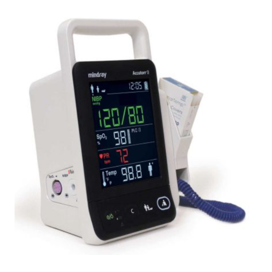
Vital signs monitor
Hide thumbs
Also See for Accutorr 3:
- Operator's manual (102 pages) ,
- Operating instructions manual (37 pages) ,
- Quick reference manual (12 pages)
Table of Contents
Advertisement
Advertisement
Table of Contents

Related Manuals for Mindray Accutorr 3


Summary of Contents for Mindray Accutorr 3
- Page 1 Vital Signs Monitor Service Manual...
- Page 3 Mindray, nor the rights of others. Mindray does not assume any liability arising out of any infringements of patents or other rights of third parties.
- Page 4 Contents of this manual are subject to changes without prior notice. All information contained in this manual is believed to be correct. Mindray is not liable for errors contained herein nor for incidental or consequential damages in connection with the furnishing, performance, or use of this manual.
- Page 5 Mindray makes no warranty whatsoever in regard to trade accessories, such being subject to the warranty of their respective manufacturers. A condition of this warranty is that the equipment or accessories which are claimed to be defective be returned when authorized, freight prepaid to Mindray DS USA, Inc., Mahwah,...
- Page 6 Contact Information Manufacturer: Shenzhen Mindray Bio-Medical Electronics Co., Ltd. Address: Mindray Building, Keji 12th Road South, Hi-tech Industrial Park, Nanshan, Shenzhen 518057 P.R. China +86 755 81888998 Tel: Fax: +86 755 26582680 Website: www.mindray.com Mindray DS USA, Inc. Distributor: Address:...
- Page 7 Preface Manual Purpose This manual provides detailed information about the assembling, dissembling, testing and troubleshooting of the equipment to support effective troubleshooting and repair. It is not intended to be a comprehensive, in-depth explanation of the product architecture or technical implementation. Observance of the manual is a prerequisite for proper equipment maintenance and prevents equipment damage and personnel injury.
- Page 8 FOR YOUR NOTES...
-
Page 9: Table Of Contents
Contents 1 Introduction ......................1-1 1.1 Manual Information ......................... 1-1 1.2 Safety Information ........................1-1 1.2.1 Warnings ......................... 1-2 1.2.2 Cautions .......................... 1-2 1.2.3 Notes ..........................1-2 1.3 Equipment Symbols ........................ 1-3 2 Theory of Operation ....................2-1 2.1 Overview ............................2-1 2.2 Connectors for Peripheral Devices .................. - Page 10 4.4.1 Entering/Quitting Maintenance Mode ............. 4-10 4.4.2 Checking Version Information ................4-12 4.4.3 Restoring Factory Default Configuration ............4-13 5 Troubleshooting ....................... 5-1 5.1 Overview ............................. 5-1 5.2 Parts Replacement ........................5-1 5.3 Troubleshooting Guide ......................5-1 5.3.1 Power On/Off Failure ....................5-1 5.3.2 Display Failures ......................
- Page 11 7.3.2 Parts List .......................... 7-3 7.4 Main Bracket Assembly ......................7-4 7.4.1 Exploded View ......................7-4 7.4.2 Parts List .......................... 7-5 7.5 Power Management Board Assembly ................7-5 7.5.1 Exploded View ......................7-5 7.5.2 Parts List .......................... 7-6 7.6 Parameter Connector Panel Assembly................7-6 7.6.1 Exploded View ......................
- Page 12 FOR YOUR NOTES...
-
Page 13: Introduction
WARNING All installation operations, expansions, changes, modifications and repairs of this product are conducted by Mindray authorized personnel. There is high voltage inside the equipment. Never disassemble the equipment before it is disconnected from the AC power source or the battery. -
Page 14: Cautions
1.2.3 Notes NOTE Refer to operator’s manual for detailed operation and other information. 1.2 Equipment Symbols See the Accutorr 3 Operator's Manual for information about the symbols used on this product and its packaging. -
Page 15: Theory Of Operation
Theory of Operation 2.1 Overview The monitor is intended for spot-check monitoring physiologic parameters, including SpO Pulse Rate, NIBP and Temperature, on adult, pediatric, and neonatal patients in healthcare facilities by clinical physicians or appropriate medical staff under the direction of physicians. 2.2 Connectors for Peripheral Devices Input/Output connector (RS-232 connector) This connector is used for software upgrade and DIAP communication. -
Page 16: Main Unit
2.3 Main Unit The main unit of the vital signs monitor consists of three parts: Front housing assembly, consisting of main board, segment-code display, and Power On/Off keypad; Rear housing assembly: power module (AC/DC), power management and interface board (including SpO isolation power), battery, NIBP module, and SpO board;... -
Page 17: Front Housing Assembly
2.4 Front Housing Assembly Main Board Keypad Main Board The main board is the control center of the equipment. It provides communication and display functions, including: Communication with SpO board, and NIBP module through serial ports, starting parameter measurement, and reading measured results; ... -
Page 18: Rear Housing Assembly
2.5 Rear Housing Assembly Power management and interface board AC/DC power module board Battery compartment NIBP module Rear housing assembly consists of power module (AC/DC), power management and interface board (including SpO isolation power), battery compartment, NIBP module, and board. AC/DC Power Module The AC/DC power board transforms the input AC into DC power, and is the power source for all voltages in the equipment. -
Page 19: External Module
2.6 External Module An external Temperature module can be mounted on the monitor. The independently developed Mindray Temperature module consists of an isolation power board, Temperature measurement board, and probes. The Temperature measurement board collects Temperature signals, processes algorithm and sends measurement results to... - Page 20 FOR YOUR NOTES...
-
Page 21: Equipment Installation
All the optional parts purchased by the customer have been received. Notify Mindray North America if your order is not correct or is incomplete. In case of damage during transportation, keep the packing material and notify the Mindray North America immediately. -
Page 22: Electrical Requirements
Wall-mount Bracket Instructions for Use (PN: 0010-20-42933) and Rollstand Instructions for Use (PN: 0010-20-42934). CAUTION Use only Mindray supplied or approved mounting solutions. The mounting bracket should be installed by qualified service personnel. 3.4 Preparation for Power on... -
Page 23: Testing And Maintenance
The testing procedures provided in this chapter are intended to verify that the equipment meets the performance specifications. If the equipment or a module fails to perform as specified in any test, repairs or replacements must be done to correct the problem. If you have any questions, contact Mindray Technical Support. CAUTION ... -
Page 24: Performance Tests
4.2 Performance Tests Performance test are designed to ensure that measurement results are accurate. The following sections provide a list of performance and accuracy tests and their recommended frequencies. 4.2.1 Performance Test Frequencies Check/Maintenance Item Recommended Frequency Visual Inspection When first installed or reinstalled. test 1. - Page 25 Measurement validation The SpO accuracy has been validated in human studies against arterial blood sample reference measured with a CO-oximeter. Pulse oximeter measurements are statistically distributed, and only about two-thirds of the measurements can be expected to fall within the specified accuracy compared to CO-oximeter measurements. NOTE ...
-
Page 26: Nibp Test
4.2.4 NIBP Test 4.2.4.1 Leakage Test NOTE Perform NIBP leakage test before any other NIBP test and calibration. Tools required: Adult NIBP Cuff NIBP Hose Cylinder Follow this procedure to perform the leakage test: Press the button to set the patient category to adult ( ). - Page 27 When the NIBP leak test is completed, the cuff will deflate automatically. is displayed in the error code area, it indicates the NIBP leak test is passed and that the system has no leak. If is displayed, it indicates the system may have a leak. Check the tubing and connections for leakages.
- Page 28 Compare the manometer values with the monitor values. The difference between the manometer and displayed values should be ± 3 mmHg. If it is greater than ± 3 mmHg, contact Mindray Technical Support. Raise the pressure in the metal vessel to 200 mmHg with the manometer bulb.
- Page 29 NIBP cuff overpressure test is passed. If is displayed, the NIBP cuff overpressure test is failed. If the test is failed, contact Mindray our your service personnel. NOTE You can use an NIBP simulator to replace the manometer bulb and the...
-
Page 30: Temperature Test
4.2.5 Temperature Test Required Tool: Thermostatic oil tank(HART 7102 recommended) or Water Bath and Precision Thermometer for reference. Test procedure: Set the temperature of the oil tank or water bath to 37°C and conduct the test after the temperature stabilizes. Set temperature unit to °C. -
Page 31: Electrical Safety And Other Tests
4.3 Electrical Safety and Other Tests 4.3.1 Electrical Safety and Other Test Frequencies Check/Maintenance Item Recommended Frequency 1. Following any repair or replacement. 2. If monitor is physically damaged. Electric safety tests 3. Every two years. For details, refer to Appendix A Electrical Safety Inspection. -
Page 32: Battery Check
4.3.4 Battery Check Required Tool: None Functional Test If the equipment is installed with a battery, remove the battery first. Verify that the equipment works correctly when running powered form an AC source. Insert the battery per the procedures provided in the operator’s manual. Remove the AC power cord and verify that the equipment still works correctly. - Page 33 Mode Keys and Functions Clear the flashing SpO sensor indicator. When a parameter label flashes due to the module failure, stop the flashing. Disable the Low Battery audio indicator. : Press and hold for above 2 seconds to enter Parameter Setup mode.
-
Page 34: Checking Version Information
Mode Keys and Functions Working Time Check the total working time. : Decrease screen brightness. Brightness Setup : Increase screen brightness. DIAP Communication Setup (PR parameter area displays : Toggle between 9600 and 19200 bps. “001”) 4.4.2 Checking Version Information Entering Maintenance mode. -
Page 35: Restoring Factory Default Configuration
Temperature module “502” indicates version 5.0.2 version Power management “011” indicates version 01.01 software version 4.4.3 Restoring Factory Default Configuration Entering Maintenance mode. Press the button and switch to restore factory default configuration interface. In the PR parameter area, code 000 is displayed. Press the button to change settings. - Page 36 FOR YOUR NOTES 4-14...
-
Page 37: Troubleshooting
Troubleshooting 5.1 Overview In this chapter, equipment problems are listed along with possible causes and recommended corrective actions. Refer to the tables to check the monitor, identify and eliminate the troubles. The troubles we list here are common difficulties and the actions we recommend can correct most problems. -
Page 38: Display Failures
5.3.2 Display Failures Symptoms Possible Cause Troubleshooting 1. Check if the cable between the display and main board and the backlight cable are correctly connected. Cable defective 2. Check that the cables and connectors are not The display is damaged. blank or black. -
Page 39: Module Defective
NOTE When the battery module has a failure, it may cause problems to other components. In this case, troubleshoot the battery module per the procedure described in the table above. Components of the main unit are powered by the power module. In the event that a component malfunctions, check if the operating voltage is correct. - Page 40 FOR YOUR NOTES...
-
Page 41: Disassembly And Repair
Disassembly and Repair 6.1 Tools Required To disassemble and replace the parts and components, the following tools may be required: Philips screwdrivers Tweezers Sharp nose pliers Clamp 6.2 Preparations for Disassembly Before disassembling the equipment, finish the following preparations: ... -
Page 42: Disassembling The Main Unit
6.3 Disassembling the Main Unit NOTE To disassemble the equipment, place the equipment on a work surface free from foreign material, avoiding damaging the screen. All the operations should be performed by qualified service personnel only. Operations relating to optional parts may not apply to your equipment. 6.3.1 Disassembling the Temperature Module (Optional) Lay the monitor on a table as shown below. -
Page 43: Removing The Parameter Connector Panel Assembly
Stand the monitor and separate the front housing assembly and rear housing assembly with caution. Disconnect the cable between the main board and power management board and then remove the front panel. NOTE When reassembling the equipment, be sure to check if the front housing waterproof strip is correctly placed. -
Page 44: Disassembling The Main Bracket Assembly
6.3.4 Disassembling the Main Bracket Assembly Unscrew the four PT3×8 screws as indicated below. Then remove the main bracket assembly. -
Page 45: Removing The Parameter Board
6.3.5 Removing the Parameter Board (SpO Optional) and Power Management Board Unscrew the two M3×6 screws and two external hexagon screws, and remove the power management board assembly from the main bracket assembly. 2 M3 screws 2 external hexagon screws Unscrew the two M3×4 screws and remove the parameter board from the power management board assembly. -
Page 46: Disassembling Pumps And Valves
6.3.6 Disassembling Pumps and Valves Cut the two cable ties and remove the NIBP pump. Cable tie Unscrew the two M3×6 screws as indicated and remove the valve. 6.3.7 Disassembling AC/DC Power Board and Battery Converter Board Unscrew the four M3×6 screws as indicated and remove the AC/DC power board. -
Page 47: Disassembling The Front Housing Assembly
Unscrew the two M3 nuts to remove the battery interface board. 6.4 Disassembling the Front Housing Assembly NOTE To disassemble the equipment, place the equipment on a work surface free from foreign material, avoiding damaging the screen. Remember to install the screen support pad properly during reassembly. ... -
Page 48: Removing The Display
6.4.2 Removing the Display Unscrew the four M3×8 screws as indicated below. Remove the display assembly. Then unscrew the four PT2×6 and remove the display. 4 M3 screws 4 PT2 screws Display 6.4.3 Removing the Keypad Unscrew the Two PT3×8 screws indicated below and remove the keypad. Keypad... -
Page 49: Disassembling The Temperature Module (Optional)
6.5 Disassembling the Temperature Module (Optional) 6.5.1 Removing the Temperature Module PCBA and Temperature Module Power Board PCBA Unscrew the 2 M3 screws indicated below and remove the metal sheet. Disconnect the Temperature board cable and the cable between Temperature isolation power board and Temperature board. - Page 50 Unscrew the four M2 screws as indicated below and remove the Temperature on-position detection board PCBA. Temperature on-position detection board PCBA NOTE Remember to assemble the silicon button for the Temperature on-position detection switch during reassembly. 6-10...
-
Page 51: Parts
Parts 7.1 Introduction This section contains the exploded views and parts lists of the main unit. It helps the engineer to identify the parts during disassembling the monitor and replacing the parts. This manual is based on the maximum configuration. Your equipment may not have same parts and the quantity of the screws or stacking sleeves etc. -
Page 52: Parts List
Screw, Pan Head W/Washer Phillips M04-004012--- M3X6 Pump Shock absorption cushion for 801-9261-00040-00 pump Fixing strip front housing Accutorr 3 front housing assembly 115-022920-00 assembly FRU Battery door assembly 115-018252-00 Predictive Temperature module 115-017687-00 Screw, pan head, Phillips M3X8 M04-000605---... -
Page 53: Front Housing Assembly
Item FRU part Description Remarks number Waterproof strip for front and rear housing front cover 115-022919-00 Accutorr 3 Front housing Display lens Keypad PCBA 051-001358-00 Keypad board cushion 115-020467-00 Keypad board adjusting sleeve Short poron cushion Long poron cushion 115-018251-00... -
Page 54: Main Bracket Assembly
Item FRU part Description Remarks number Screw, PT2X6 M04-051003--- ST3.3X8 screw 030-000338-00 Screw, pan head cross recessed M3X6 M04-004012--- Main board PCBA 051-001363-00 Accutorr 3 silicon buttons 049-000606-00 7.4 Main Bracket Assembly 7.4.1 Exploded View... -
Page 55: Parts List
7.4.2 Parts List Item FRU part Description Remarks number With 6301 battery interface PCBA 115-018254-00 cable Knob, Battery latch 0380-00-0593 AC input receptacle and cable 009-003241-00 Power board shield 047-010575-00 Power board 022-000125-00 Power board insulator 047-010364-00 Cable between the power management board 009-003237-00 and power board 7.5 Power Management Board Assembly... -
Page 56: Parts List
7.5.2 Parts List Item FRU part Description Remarks number Power management board 115-018256-00 service kit (without Masimo PCBA, Power receptacle) management/interface Power management board board 115-018257-00 service kit (with Masimo receptacle) shield 047-010576-00 100-000106-00 Nellcor SpO board (MDU) board 040-000109-01 board, Masimo MS-2013 7.6 Parameter Connector Panel Assembly 7.6.1 Exploded View... -
Page 57: Predictive Temperature Assembly
7.7 Predictive Temperature Assembly 7.7.1 Exploded View 7.7.2 Parts List Item Description FRU part number Screw, Pan head w/washer M04-004012--- Predictive Temperature module power board PCBA 801-6006-00043-00 Predictive Temperature housing 043-003327-01 Temperature on-position detection board PCBA 051-001419-00 External compartment for Temperature module 043-003312-01 Temperature cover 049-000547-01... - Page 58 Item Description FRU part number Screw, pan head cross recessed M2X6 M04-051003--- Screw, Flat Head Phillips, M3X6 M04-005005--- Predictive Temperature module PCBA 051-001435-00 Predictive Temperature board cable 009-003368-00 Cable between the Temperature module and power 009-003239-00 management board Cable between the isolation power board and 009-003240-00 Temperature board...
-
Page 59: Hardware And Software Upgrade
Hardware and Software Upgrade 8.1 Hardware Upgrade The vital signs monitor supports upgrade of NIBP, SpO and Temperature functions. 8.1.1 Upgrade Package Upgrade package Description of upgrade package PN of upgrade package Masimo SpO upgrade kit 115-023200-00 Nellcor SpO upgrade kit 115-018267-00 Temp Temperature module... -
Page 60: Upgrading Temp
PR parameter area: means "SpO module is configured on this equipment" while means the contrary. Restart the monitor. 8.2 Software Upgrade Software upgrades must be performed by Mindray, NA authorized service personnel. Call Service Dispatch 1 800 288-2121 ext: 7875. -
Page 61: A Electrical Safety Inspection
Electrical Safety Inspection The following electrical safety tests are recommended as part of a comprehensive preventive maintenance program. They are a proven means of detecting abnormalities that, if undetected, could prove dangerous to either the patient or the operator. Additional tests may be required according to local regulations. -
Page 62: Device Enclosure And Accessories
A.2 Device Enclosure and Accessories A.2.1 Visual Inspection Test Item Acceptance Criteria No physical damage to the enclosure and accessories. No physical damage to meters, switches, connectors, etc. The enclosure and accessories No residue of fluid spillage (e.g., water, coffee, chemicals, etc.). No loose or missing parts (e.g., knobs, dials, terminals, etc.). - Page 63 ELECTRICAL SAFETY INSPECTION FORM Overall assessment Scheduled inspection Test item: 1, 2, 3, 4, 5, 6, 7 Unopened repair type Test item: 1, 2, 3 Opened repair type, not replace the power part including Test item: 1, 2, 3, 4 transformer or patient circuit board Opened repair type, replace the power part including Test item: 1, 2, 3, 4, 5...
- Page 64 FOR YOUR NOTES...
- Page 66 PN: 046-005295-00 (3.0)
Need help?
Do you have a question about the Accutorr 3 and is the answer not in the manual?
Questions and answers