
Related Manuals for Sunny SF-B2706


Summary of Contents for Sunny SF-B2706
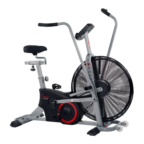
- Page 1 TORNADO AIR BIKE SF-B2706 USER MANUAL IMPORTANT! Read all instructions carefully before using this product. Retain owner’s manual for future reference. For customer service, please contact: support@sunnyhealthfitness.com...
-
Page 2: Important Safety Notice
IMPORTANT SAFETY NOTICE We thank you for choosing our product. To ensure your safety and health, please use this equipment correctly. It is important to read this entire manual before assembling and using the equipment. Safe and effective use can only be assured if the equipment is assembled, maintained, and used properly. It is your responsibility to ensure that all users of the equipment are informed of all warnings and precautions. -
Page 3: Exploded Diagram
EXPLODED DIAGRAM... -
Page 4: Parts List
PARTS LIST DESCRIPTION DESCRIPTION Main frame 20L/R Rear end cap 1.pr Cross pan head screw Handlebar ST4.2*18 Seat tube Central axle Screw Slide rail Bearing 5L/R Swing Tube 1.pr Bolt Foot tube Hex thin nut M8*H5 Connecting tube Bearing 8L/R Small crank 1.pr Nylon nut M8... -
Page 5: Assembly Instruction
ASSEMBLY INSTRUCTION STEP 1 1. Disassemble the Hex Pan Head Screws (16), Spring Washers (17) and Flat washers (18) from the Front Stabilizer (9) and Rear Stabilizer (10). 2. Attach the Front Stabilizer (9) and the Rear Stabilizer (10) to the Main Frame (1) with the Hex Pan Head Screws (16), Spring Washers (17) and Flat washers (18) again. - Page 6 STEP 2 1. Disassemble the Bolts (24), Hex Thin Nuts (25) and Nylon Nuts (27) from the Swing Tube (5L/R). 2. Attach the Pedal Tube Axle (31) of the Swing Tube (5L/R) to the two sides of the Main Frame (1).
- Page 7 STEP 3 Attach the Pedal (11L/R) to the Crank (13L/R) with the cross wrench. NOTE: Make sure to attach Right Pedal, marked (R), to the Right Crank (R). It should be tightened clockwise. Attach the Left Pedal, marked (L), to the Left Crank (L). It should be tightened counterclockwise.
- Page 8 STEP 4 1. First, disassemble the Hex Pan Head Screws (16), Spring Washers (17) and Flat Washers (18) from the Main Frame (1). Thread the Sensor Wire (38) from the bottom of the Handlebar Post (2) and bring out from the top. Then attach the Handlebar Post (2) to the Main Frame (1) with Hex Pan Head Screws (16), Spring Washers (17) and Flat Washers (18).
- Page 9 Moving the Bike Lift the bike by the Rear Stabilizer (10) until the wheels on the Front Stabilizer (9) touch the floor. Now you can move the bike.
-
Page 10: Exercise Computer Instructions
EXERCISE COMPUTER INSTRUCTIONS DISPLAY FUNCTIONS ITEM DESCRIPTION -Display the rotations per minute with range from 0~ 199. SPEED -Display current training speed. Maximum speed is 99.9 KM/H or ML/H. TIME -Count up - Time will count up from 00:00 to maximum 1:59:59 in 1 minute increments. -
Page 11: Operating Instructions
OPERATING INSTRUCTIONS Age – The first time you turn on the meter, AGE will flash. Use arrow keys to set age. Press ENTER to confirm. Meter will be in standby mode. To set Kilometer or Mile, press and hold STOP and ENTER key at the same time for 2 seconds. Press arrow key to select KM or M. - Page 12 BATTERIES This meter use 2 AA batteries. If there is a problem with the display, try changing the batteries. When changing the batteries, change both of them. Do not mix battery types or old and new batteries. Dispose of batteries according to your regional guidelines. Version 1.1...
Need help?
Do you have a question about the SF-B2706 and is the answer not in the manual?
Questions and answers