
Related Manuals for Casio PX-780


Summary of Contents for Casio PX-780
- Page 1 SERVICE MANUAL HANDHELD TERMINAL IT-3100 Series (PX-780) JUL. 2008 Ver.4 : Feb. 2011 INDEX...
-
Page 2: Table Of Contents
THEY ASSUME NO RESPONSIBILITY OR LIABILITY FOR ANY ERRORS OR INACCURA- CIES THAT MAY APPEAR IN THIS PUBLICATION NOR ARE THEY IN ANYWAY RESPON- SIBLE FOR ANY LOSS OR DAMAGE RESULTING FROM THE USE (OR MISUSE) OF THIS PUBLICATION. • Bluetooth is a trademark owned by Bluetooth SIG,Inc.and licensed to CASIO COMPUTER CO., LTD. • Microsoft and Windows are either registered trademarks or trademarks of Microsoft Corporation in the United States and/or other countries. • Other company names and product names used in this document are trademarks or registered... -
Page 3: Precautions
W hen the product power is turned on, the protection timer may stop charging the rechargeable battery pack, which may not yet be in full charge, 10 hours after the start of charging. CAUTION RISK OF EXPLOSION IF BATTERY IS REPLACED BY AN INCORRECT TYPE. DISPOSE OF USED BATTERIES ACCORDING TO THE INSTRUCTIONS. Printer, Printing, Paper U se printer paper recommended by CASIO. P erform paper width setting (58mm/80mm) before using the printer for the first time. D o not mix paper of the different paper widths (58m/80mm) when using the printer. Doing so may damage the printer. Printing onto paper of the width of 80mm cannot be done after printing onto paper of the width of 58mm. A ttach an optional holder for cut paper when using cut paper. -
Page 4: General
1. GENERAL 1-1. Product Concept IT3100, a model enhanced from the IT-3000 series on the functions below, shall be the key product line that represents CASIO-brand handheld terminals. (1) Upgraded OS • Windows CE5.0 is installed •VS2005 is available for use •The device control library (abstraction library) facilitate the development of applications. (2) Higher visibility in outdoors •Adapting the high-visibility LCD (3) Larger RAM size •Increased to 128MB (4) Upgraded Bluetooth •Upgraded from Ver1.1 to Ver1.2 (Sep. 2009) •Upgraded from Ver1.2 to Ver2.0 (Dec. 2010) - Page 5 1-3. Options Product Descriptions HA-B61IO Bridge Satellite Cradle HA-B30CHG Cradle-type Battery Charger HA-B34AT Battery Charger Car Mount Unit DT-827CAC Car Power Cable DT-9723LIC Lithium-ion Battery Pack 7.4V 2,200mAh DT-9721CHGE Single Battery Charger AD-S42120AE AC Adaptor for HA-B61IO, HA-B30CHG INPUT: 100V-240V AC 50/60Hz OUTPUT: 12V DC 3.5A DT-9020ADP-GS AC Adaptor for IT-3000 DT-9020ADP-US AC Adaptor for IT-3000 INPUT: 230VAC 50Hz (DT-9020ADP-GS) 120VAC 60Hz (DT-9020ADP-US) OUTPUT: 9.0V DC DT-887AXA RS-232C Cross Cable for connecting PC and Bridge Satellite Cradle. DT-888RSC RS-422 Modular Cable for connecting Bridge Satellite Cradles. – 3 –...
- Page 6 Product Descriptions DT-380USB USB Cable for connecting PC and Bridge Satellite Cradle HA-B80AX RS-232C Cross Cable for connecting PC and IT-3000. HA-B93PH Paper Holder HA-B92PCV Splash Protect Cover HA-B90DCV Screen Protect Cover – 4 –...
-
Page 7: Specifications
2. SPECIFICATION 2-1. System Requirements IT-3100M53E/ IT-3100M54E/ IT-3100M55E/ IT-3100M56E/ MODEL IT-3100M55U IT-3100M56U M53E2 M54E2 M55E2 M56E2 Marvell ® PXA255 Application Processor (400 MHz max.) ® ® Microsoft Windows CE 5.0 operating system Memory 128MB 96MB ROM (user defined: Approx. 30MB) Display Type 3.5-inch, 2-Way TFT Color LCD... - Page 8 IT-3100M53E/ IT-3100M54E/ IT-3100M55E/ IT-3100M56E/ MODEL IT-3100M55U IT-3100M56U M53E2 M54E2 M55E2 M56E2 Printer Type Drop-in thermal line dot printer Effective Printing Width 72 mm (80mm/82.5mm wide paper)/48 mm (58 mm wide paper) Printing Speed 28 lines/second Printable Characters ANK, symbologies (JAN/UPC-E/ NW-7/Code-39/ITF/Code-128), OCRB, 128 non-standard characters Character Fonts Kanji 12-dot 48/32 columns, 16-dot 36/24 columns, 24-dot 24/16 columns (columns shown for 80 mm wide paper and 58 mm wide paper, respectively)
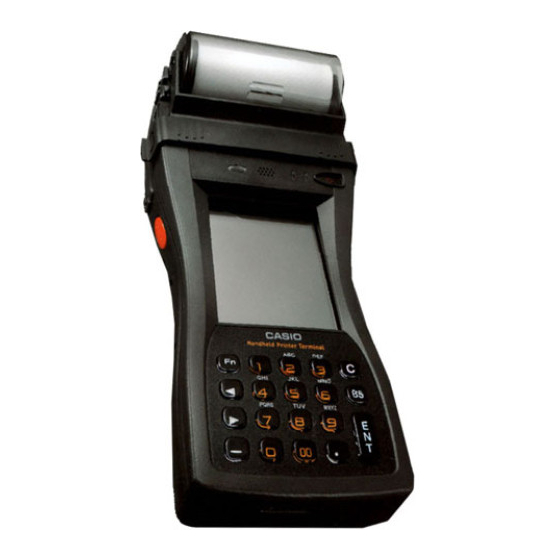
- Page 9 2-2. Part Name SD Memory Card Slot Slot for inserting SD memory card. Program Key (L) This key can be assigned any function available. IT-3100M55E/M55E2/M55U/M56E/M56E2 The default settings are as follows. This key is used to read bar codes and 2D code. Roll Paper Holder Roll paper is placed in this holder.
-
Page 10: Key Functions
2-3. Key Functions 1 Fn Key This key is used to switch the character input mode or make various settings in combi- nation with other keys, or start up a pre-registered application. 2 Numeric Keys These keys are used to input numbers and letters. (Cursor Key) Moves the cursor to the left. (Cursor Key) Moves the cursor to the right. This is also used to feed paper when pressed after pressing the Fn key when printing paper is loaded. This key is pressed when inputting a hyphen or bar. This key is pressed when inputting a decimal point. This key is pressed when canceling an operation and input. 8 BS This key is pressed when deleting the character to the left of the cursor. 9 ENT This key is pressed when entering an input. * Each numeral and symbol on the key buttons in the table above is backlit. – 8 –... -
Page 11: Technical Information
3. TECHNICAL INFORMATION 3-1. WIRING DIAGRAM Scanner Printer 22pin 30pin Paper CN19 PCMCIA CN20 Sensor CARD 8pin I/F Speaker CN13 CN800 PCMCIA Illuminance Power sensor Touch Panel CONNECTOR LED LED CN11 68pin 14pin I/F CN801 Back light CN12 CARD Sub Battery CN22 CN15 MAIN PCB... - Page 12 3-2. SYSTEM DIAGRAM IT-3100 seies RS-232C Serial I/F Cross cable HA-B80AX 14pin Support device serial I/F IrDA Purinter RS-232C IrDA 1.1 I/O box RS-422 RS-422 HA-B61IO AC adaptor I/O box AD-S42120AE HA-B61IO Cradle-type Power supply Battery Chaeger terminal HA-B30CJG AC adaptor AD-S42120AE AC adaptor AD-S42120AE...
- Page 13 3-3. MAIN PCB VIEW CN20 CN13 CN11 CN19 CN801 CN22 CN15 CN800 CN14 CN12 CN24 CN28 CN29 CN16 Symbol Description To Bluetooth Antenna From Touch Panel To 2D Scanner SD Card Slot CN11 From PW PCB CN12 To 14 pin I/F CN13 To 8 pin I/F CN14 To MCR CN15 From Trigger, Power FPC CN16 From KEY PCB CN19 To Printer CN20 To Paper Sensor CN22 To Backup battery CN24...
- Page 14 3-4. COMPONENTS LOCATION ON THE MAIN PCB – 12 –...
- Page 15 – 13 –...
-
Page 16: Troubleshooting
4. TROUBLESHOOTING 4-1. Does not turn ON Check if LCD Replace the Check the voltage and MAIN PCB is connector and BL connector MAIN PCB and placement of the battery. defective. are correctly inserted. check again. LCD connector and BL connector are Continue check. - Page 17 4-6. KEY/BUTTON NG FFC/FPC Check the connection FFC/FPC is defective. damaged? of CN15 and CN16. Check if keys are Keys are not correctly assembled. correctly assembled. Connector is loosely connected. MAIN PCB is defective. 4-7. TOUCH PANEL NG Check the connection TOUCH PANEL After replacing the TOUCH of CN3.
- Page 18 4-9. Scanner LED NG Check the connection FFC is defective. of CN11. damaged? After replacing the PW PCB is defective. PW PCB, check again. Connector is loosely connected. MAIN PCB is defective. 4-10. Sensor NG AD0-2 MAIN PCB is defective. CN11 FFC is defective.
- Page 19 4-11. Speaker NG Check the connection FFC is defective. of CN11. damaged? After replacing the Speaker is defective. Speaker, check again. Connector is loosely connected. MAIN PCB is defective. 4-12. PCMCIA Card NG Replace the MAIN PCB and check again. 4-13. SD Card NG Replace the MAIN PCB and check again. 4-14. Charge LED NG Check the connection FFC is defective.
- Page 20 4-15. IrDA NG Check if the inspection MAIN PCB is defective. tools operate normally HA-B61IO is defective. PC setting is incorrect. 4-16. 8pin I/F NG Check the connection Replace SIP FPC, SIF FPC is defective. of CN13. check again. MAIN PCB is defective. Connector is loosely connected.
- Page 21 4-18. Printer NG Check the connection Replace Printer, Battery volvage Printer is defective. of CN19. check again. 6.0V? MAIN PCB is defective. Connector is loosely Low Battery connected. 4-19. Key Backlight NG Check the connection FFC is disconnected. of CN16. damaged? Replace KEY PCB, KEY PCB is defective.
- Page 22 4-21. CMOS Imager NG Check the connection FPC damaged? FPC is defective. of Imager. Change Imager and Imager is defective. check again. Connector is loosely connected. MAIN PCB is defective. – 20 –...
-
Page 23: System Function
5. SYSTEM FUNCTION 5-1. Control of powering ON/OFF 1. Factors which turn the power ON The device is powered ON when, (1) the power key is pressed (2) it reaches the time specified by the Alarm function (3) the device is placed on the IO box (It only applies when the power is supplied by the IO box. Default setting is prohibited.) (4) the trigger key is pressed (5) the device receives a call when a communication card is attached and the card is powered on (6) the communication card is removed from the device when the WakeOn by the communication card is set to on (7) a power on request is received from a Bluetooth module (8) a power on request is received from the 14 Pin serial port (9) VDET1 occurs when WakeOn is set (The user should check the power on because canceling WakeON immediately turns the power off) * Each factor which turns on the device can be set or cancelled by using a program. 2. Factors which prevent turning on the power The following items are checked before turning the power ON, and the device is not powered ON when either of them is applicable. - Page 24 5-2. Power saving control The following power saving functions are provided with this device: 1 Idle state Saves power by making the CPU in the idle state when there is no executable event and the system and applications are waiting for a next event. Peripheral devices are in operation. 2 CPU frequency control CPU frequency can be switched between the setting to handle high-speed processing and the power saving setting. This setting can be changed by the system library and the CPU frequency of "LOW: 200MHz" or "HIGH: 400MHz" can be selected. "LOW" for the normal state is the default.
- Page 25 6 Restriction on the brightness of the backlight imposed by the temperature sensor When the temperature sensor detects the increase of the temperature on the device, it automatically restricts the brightness of the backlight. (The automatic restriction on the brightness of the backlight works when the device is battery operated and also when it is operated by an external power source). * This restriction has two phases; the first phase of the restriction on the brightness of the backlight has 8 steps, and backlight setting is restricted within these 8 steps. The second phase of the restriction has 9 steps, and backlight setting is restricted up to the 6th steps. * When the setting of the brightness in the normal state or when the automatic dimmer function works (only when the device is battery operated) is brighter than the valid range (steps) of the brightness under restriction, the backlight automatically becomes dimmer to the brightest setting within the restricted range; when the temperature of the device become lower which cancels the restriction, the brightness...
- Page 26 5-3. Low voltage monitoring There are four low voltage detection levels on the hardware of the device. Level Content Operation Action on next start-up VDET1 Warning on voltage reduction of Display of warning on ――――― main battery voltage reduction of main battery VDET2 P o w e r O F F d u e t o v o l t a g e Power OFF Resume (with warning reduction of main battery...
-
Page 27: Basic Operations
6. BASIC OPERATIONS 6-1. Attaching the Neck Strap A neck strap can be attached to the Handheld Printer Terminal to keep it from being dropped while being carried. The stylus holder provided can also be attached. Adjust length here Neck strap rings* Stylus holder Neck strap Mounting hooks Attach the neck strap following the procedure described below. Attachment Procedure 1. Pull out the neck strap mounting hooks out of each silo on the bottom of the Handheld Printer Terminal using the tip of stylus. Hook the protrusive part (**) of the ring on the neck strap mounting hook as shown in the illustration. While slightly pushing the ring, turn the ring until all part of it is fully hooked. -
Page 28: Calibrating Touch Screen Alignment
6-2. Calibrating Touch Screen Alignment Whenever you feel that touch screen response is poor or that the operations being executed do not match the location you are tapping on the touch screen, perform the following operations to calibrate the alignment of the touch screen. • Press the “Fn” key and then make sure that “F” appears in the lower right corner of the screen. If the “F” appears, press the “4” key. * The following screen can also be displayed by navigating to Start → Settings → Stylus and Calibration tab. • Press the stylus against the center of each target mark (total of five marks) as indicated on the screen. The screen shown below appears after you press stylus against the target at five different locations. • Press the ENTER key or tap anywhere on the touch screen. Adjusting Display Contrast Perform the following steps to adjust display contrast to make display colors more vivid and easier to see. • Press the “Fn” key and then make sure that “F” appears in the lower right corner of the screen. If the “F” appears, press the “2” key or “3” key. Pressing the “2” key adjusts for more contrast, while pressing the “3”... - Page 29 Adjusting Display Brightness You can use the following procedure to adjust screen brightness to make it easier to read under different lighting conditions. • Press the “Fn” key and then make sure that “F” appears in the lower right corner of the screen. If the “F” appears, press the “5” key or “6” key. Pressing the “5” key adjusts brightness for a darker display, while pressing the “6” key adjusts brightness for a brighter display. * In order to continue to make adjustments, press the “5” key or “6” key after again first pressing the “Fn” key. * Brightness settings can also be made by consecutively tapping “Brightness” on the control panel. Important! • If you use your Handheld Printer Terminal in a location where it is hot, it automatically dims the screen to protect against damage. Display Auto Dimmer The display auto dimmer automatically lowers display brightness if you do not perform any operation for a specific amount of time. This saves the battery power to be drawn. You can use the following procedure to specify the amount of time should be allowed to pass before auto dimming is performed. • Select “Control Panel” on the “Settings” menu after tapping the “Start” button in the lower left corner of the screen. Next, consecutively tap the “Brightness” icon and then tap “Backlight” to set the displayed parameters.
- Page 30 6-3. C-MOS Imager (IT-3100M55E/M55E2/M55U/M56E/M56E2/M56U only) 1. Turn on the Handheld Printer Terminal, position its C-MOS Imagerreader port near the bar code or 2D code, and then press the Trigger Key (R or L). 2. The Handheld Printer Terminal reads the code by emitting laser and red lights. Indicator 2 (read operation indicator lamp) lights in green when the reading is successful.
- Page 31 Warning Label Laser light is emitted IT-3100M55U/M56U/ from this port M55E/M55E2/ M56E/M56E2 • This label is a warning label for Class 2 laser products that comply with IEC60825-1+A2:2001 CAUTION • Use of controls or adjustments or performance of procedures other than those specified herein may result in hazardous radiation exposure. • The laser light emitted by the C-MOS Imager has a maximum output of less than 1 mW and a wavelength of 650 nm. Warning! ■ Never look directly into the laser light. • This product with the integrated laser scanning module scans bar codes using laser light. Never look directly into the laser light or shine the laser light into the eyes.
- Page 32 6-4. Magnetic Card Reader The Magnetic Card Reader comes as standard with IT-3100M54E/M54E2/M55E/M55E2/M55U. Only use cards that are compatible with the ISO standards. The procedure for reading cards is described below. 1. Remove the cover as shown in the illustration. 2.
-
Page 33: Data Communication
6-5. Data Communication IR Communication IR communication can be used to transfer data between two Handheld Printer Terminals. When performing IR communication, orient the IR ports of both Handheld Printer Terminals so they are pointing directly at each other. Data communication is possible within a distance of 0 (in direct contact) to 1 m (max. 20 cm at 4 Mbps). - Page 34 Bluetooth Communication ® Bluetooth protocol can also be used to transfer data between two ® Handheld Printer Terminals. The two Handheld Printer Terminals should be no more than three meters apart (as long as there is nothing blocking the path in between). Important! Observe the following precautions to help ensure that data communication is successful. • Make sure that the Handheld Printer Terminal are located within about three meters (16'4 ") of each other. Surroundings (obstacles) may require a shorter distance between the two terminals.
-
Page 35: Reset Operation
7. RESET OPERATION 7-1. Resetting the Handheld Printer Terminal Resetting the Handheld Printer Terminal is the same as restarting a computer. Performing a reset causes all unsaved inputs and edits to be lost, but data that is already stored in the memory as well as all settings should be unaffected. Use reset to restore normal operation whenever the Handheld Printer Terminal operates abnormally due to misoperation or some other reason. Use the stylus to press the reset switch on the back of the Handheld PrinterTerminal. This starts the reset operation. If reset does not find a memory problem The Handheld Printer Terminal restarts, and normal operation is restored. - Page 36 7-2. Performing a Full Reset (Initialization) Performing a full reset initializes memory. This means that all data stored in the memory (RAM) is deleted and all the settings are returned to their initial factory settings. Perform a full reset whenever any one of the following conditions exists. • When you want to delete all memory contents and return the settings to their initial factory settings. • When you are no longer able to use the Handheld Printer Terminal because you forgot your password. • When the Handheld Printer Terminal does not operate normally due to a memory problem. • When the message “A problem with memory contents has been found..” appears. To perform a full reset Important! Performing a full reset deletes all data currently stored in the memory (RAM). If possible, backup data of the Handheld Printer Terminal to a computer, Flash Memory, a memory card, or some other medium before performing a full reset. 1. The message shown below appears on the display when the resetswitch is pressed for about 1 second with the stylus while simultaneously pressing the power key and cancel key. the program the progra key (L) key (R) • To cancel the full reset operation, press the program key (L) instead of the program key (R). 2. Press the program key (R). This causes the message shown below to appear. the program the program key (L) key (R) • To cancel the full reset operation, press the program key (L) instead of the program key (R).
-
Page 37: Hardware Inspection
8. HARDWARE INSPECTION Before inspection, • Make sure to install the latest patch file. • Perform Model Status Setting in advance when replacing the main PCB (see page 73). 8-1. Service Utility Software Service Utility Software is a tool for hardware test and various settings. 1. How to obtain The Service Utility Software is available through the following methods. 1. Download from the following website for the Authorized Service Center. URL: https://www.servicecasio.com/manual/pdffinder.php File name: It3100.zip 2. File list The following folders and files appear by unzipping a “It3100.zip” file on computer. File List File Name Descriptions Diag780.exe Hardware inspection dnk.bin BTLineTestPX780VA.exe BTRadioTest.exe Function for testing Bluetooth BTServerPX780VA.exe BTTest.dat IDCHK780.exe ID Number Registration Utility IDSET780.EXE 2DSCANCHK.exe Function for testing 2D Scanner 2DSCANCHKForPX781.exe SetModelStatus.exe Model setting Utility 3. Copy all the files on a PCMIA Card or an SD Card. - Page 38 8-2. To boot the diagnostic program 1. Insert the card with the Service Utility Programs in Section 8-1 to IT-3100. 2. Perform full reset. 3. Perform set up according to the instructions in the display. • Touch Screen Calibration • Data/Time Properties • Owner Properties 4. Open the storage card folder, and double-tap “DIAG780”. My Computer g Storage Card g DIAG780 5. Tap the center of the display. g The diagnostic program menu appears. Menu Main Menu 1 appears when the diagnostic program is booted. There are three menu types in the Main Menu, which can be switched from one to another by the following operation. Press [ENT]. Tap [NEXT] in the display. Tap [BACK] in the display. ** Main menu 1 ** ** Main menu 2 ** ** Main menu 3 ** Tap [NEXT] Tap [NEXT] 1.SDRAM 1.ASK/IrDA...
- Page 39 8-3. Function Test Inspection Item Table Target Models Inspection Inspection Items Inspection Tool M55E/M55E2 M56E/M56E2 Guide M53E/M53E2 M54E/M54E2 (M55U) (M56U) SDRAM P.38 NAND-FROM P.39 KEY/BUTTON P.40 TOUCH PANEL P.41 P.42 Scanner LED P.45 Sensor P.46 Speaker P.49 PCMCIA Card PCMCIA Storage Card P.50 SD Card SD Storage Card...
- Page 40 Operation Guide No.1 SDRAM Operation Display Inspection contents Tap "1.SDRAM" ** SDRAM CHECK ** or 1.SDRAM CHECK push "1" key. 2.SDRAM CHECK (Loop) 3.SDRAM CHECK (Off On) 4.SDRAM CHECK (Write) 5.SDRAM CHECK (Read, Compare) [Exit] or Enter Key Tap "1.SDRAM CHECK" ===== SDRAM CHECK ===== Write → Read → Verify the patterns of 0x5555AAAAH or RAM SIZE = xxMbyte and 0xAAAA5555H outside Start addr = xxxxxx push "1" key. the OS work area. Chk byte = xxxxxx RAM Check Start. Confirm the display on the left. Write/Read/Verify 0x5555AAAA Write/Read/Verify 0xAAAA5555 -- RAM CHK OK --...
- Page 41 No.2 NAND-FROM Operation Display Inspection contents Tap "2.NAND-FROM" ** NAND-FROM CHECK ** 1.NAND-FROM CHECK push "2" key. 2.NAND-FROM CHECK (Loop) [Exit] or Enter Key Tap "1.NAND-FROM CHECK" ** NAND-FROM CHECK ** Write → Read → Verify NAND-FROM FROM TYPE (SAMSUNG) FROM SIZE (33554432 Byte) push "1" key. Confirm the display on the left. Now checking . . . Check Finished. FROM Write Check : OK [Exit] or Enter Key Tap [Exit] ** NAND-FROM CHECK ** Confirm the display on the left.
- Page 42 No.3 KEY/BUTTON Operation Display Inspection contents Tap "3.KEY/BUTTON" ====== Key Test ====== [ Fn] [ENT] [ <] [BCK] push "3" key. [ >] [CNL] [ -] [ 0] [ 1] [ 2] [ 3] [ 4] [00] [ 5] [ TRG(L)] [TRG(R)] Confirm that "OK" is displayed Push corresponding keys to ====== Key Test ====== corresponding to the input keys. the "wait" display.
- Page 43 No.4 TOUCH PANEL Operation Display Inspection contents Tap "4.TOUCH PANEL" ** TOUCH PANEL CHECK ** 1.Point push "4" key. 2.Point2 3.Dot Line [Exit] or Enter Key Tap "1.Point" + ** Point ** push "1" key. P ush Center of Cross E xit:Push Enter Key + Tap a point indicated by "+". Tapped "+" goes off. Confirm the display on the left. Tap ALL "+" points. ** Point ** Confirm the display on the left. Push Center of Cross Exit:Push Enter Key Touch Panel -----> OK Tap the screen ** TOUCH PANEL CHECK ** Confirm the display on the left.
- Page 44 No.5 LCD (1/3) Operation Display Inspection contents Tap "5.LCD" ** LCD CHECK ** 1.Fill VRAM push "5" key. 2.Pattern 3.Color Bar 4.Scroll 5.Adjust (VCOM) 6.Adjust (LED BL) [Exit] or Enter Key Tap "2.Pattern" Confirm the display on the left. push "2" key. Tap the screen Confirm the display on the left. Push "Enter" key. Tap the screen Confirm the display on the left (check) Push "Enter" key. – 42 –...
- Page 45 No.5 LCD (2/3) Operation Display Inspection contents Tap the screen Confirm the display on the left (inverse check) Push "Enter" key. Tap the screen Confirm the display on the left. Push "Enter" key. Tap the screen Confirm the display on the left. Push "Enter" key. Tap the screen Confirm the display on the left. Push "Enter" key. – 43 –...
- Page 46 No.5 LCD (3/3) Operation Display Inspection contents Tap the screen Confirm the display on the left. Push "Enter" key. Tap the screen Confirm the display on the left. Push "Enter" key. Tap the screen ** LCD CHECK ** Confirm the display on the left. 1. Fill VRAM Push "Enter" key. 2. Pattern 3. Color Bar 4. Scroll 5. Adjust (VCOM) 6. Adjust (LED BL) [Exit] or Enter Key Tap [Exit] Confirm the display on the left. Back to Main Menu 1 push "Enter" key. – 44 –...
- Page 47 No.6 Scanner LED Operation Display Inspection contents Tap "6.LED" ** LED ** 1.Scanner LED push "6" key. 2.Scanner LED (Loop) [Exit] or Enter Key ** Scanner LED ** Confirm that Tap "1.Scanner LED" Scanner LED lights in red. push "1" key. Scanner LED ON (Red) Hit Any Key. Tap the screen ** Scanner LED ** Confirm that Scanner LED lights in green. push ANY key. Scanner LED ON (Green) Hit Any Key. Tap the screen ** Scanner LED ** Confirm that Scanner LED lights in orange. push ANY key. Scanner LED ON (Both) Hit Any Key. Tap the screen ** LED ** Confirm the display on the left. 1.Scanner LED push ANY key.
- Page 48 No.7 Sensor_1 Operation Display Inspection contents Tap "7.Sensor" ** Sensor ** 1.Sensor1 push "7" key. 2.Sensor2 [Exit] or Enter Key Tap "1.Sensor1" ** Sensor1 ** Battery Voltage (GLOB) LCD Temperature (GLOB) push "1" key. CPU Temperature (GLOB) Bright Sensor (GLOB) [Exit] or Enter Key Confirm the Battery Voltage ** Sensor1 ** The Battery Voltage (GLOB) (GLOB) value. Battery Voltage (GLOB) value must be in 500 - 600. LCD Temperature (GLOB) CPU Temperature (GLOB) Confirm the LCD Temperature The LCD Temperature (GLOB) (GLOB) value. Bright Sensor (GLOB) value must be in 150 - 350. Confirm the CPU Temperature The CPU Temperature (GLOB) (GLOB) value. value must be in 150 - 350.
- Page 49 No.7 Sensor_2 (1/2) Operation Display Inspection contents Tap "7.Sensor" ** Sensor ** 1.Sensor1 push "7" key. 2.Sensor2 [Exit] or Enter Key Tap "2.Sensor2" ** Sensor2 ** The Printer Head Voltage Printer Head Voltage xxxx value must be in 2500 - 3500. Printer Head Temperature xxxx push "2" key. Paper Sensor (Front) xxxx Paper Sensor (Back) xxxx Confirm the Printer Head Volt- age value. [Exit] or Enter Key Confirm the Printer Head Tem- ** Sensor2 ** The Printer Head value must be perature value. Printer Head Voltage xxxx in 500 - 2000. Printer Head Temperature xxxx Paper Sensor (Front) xxxx...
- Page 50 No.7 Sensor_2 (2/2) Operation Display Inspection contents Set the printer paper. ** Sensor2 ** Paper Sensor (Front) 3000 or Confirm "Paper Sensor (Front)" Printer Head Voltage xxxx more. and "Paper Sensor (Back)" Printer Head Temperature xxxx Paper Sensor (Back) 2400 or value. Paper Sensor (Front) xxxx more. Paper Sensor (Back) xxxx [Exit] or Enter Key Tap [Exit] Back to Sensor Menu Confirm the display on the left. push "Enter" key. Tap [Exit] Back to Main Menu 1 Confirm the display on the left. push "Enter" key. – 48 –...
- Page 51 No.8 Speaker Operation Display Inspection contents Tap "8.Audio" ** Speaker ** 1.Wave 20 Hz push "8" key. 2.Wave 1.0 kHz 3.Wave 3.0 kHz 4.Wave 10 kHz 5.Wave 20 kHz [Exit] or Enter Key Tap "5.Wave 20kHz" ** AUDIO 20kHz ** Confirm that the volume is turned up in five levels. push "5" key. [Exit] or Enter Key Tap [Exit] Back to Speaker Menu Confirm the display on the left. push "Enter" key. Tap [Exit] Back to Main Menu Confirm the display on the left. push "Enter" key. – 49 –...
- Page 52 No.9 PCMCIA Card Operation Display Inspection contents Tap "9.PCMCIA Card" ** PCMCIA Card ** 1.PCMCIA Card CHECK push "9" key. 2.PCMCIA Card CHECK (Loop) [Exit] or Enter Key ** PCMCIA CHECK ** Tap "1.PCMCIA Card CHECK" Confirm the display on the left. Now checking . . . push "1" key. Check finished. PCMCIA Slot · · · OK [Exit] or Enter Key Tap [Exit] ** PCMCIA Card ** Confirm the display on the left. 1.PCMCIA Card CHECK push "Enter" key. 2.PCMCIA Card CHECK (Loop) [Exit] or Enter Key Tap [Exit] Back to Main Menu Confirm the display on the left. push "Enter" key. – 50 –...
- Page 53 No.10 SD Card Operation Display Inspection contents Insert a SD memory card. Tap "0.SD Card" ** SD Card ** 1.SD Card CHECK push "0" key. 2.SD Card CHECK (Loop) [Exit] or Enter Key Tap "1.SD Card CHECK" ** SD Card CHECK ** Confirm the display on the left. Now checking . . . push "1" key. Check Finished. SD Slot · · · OK [Exit] or Enter Key ** SD Card ** Confirm the display on the left. Tap [Exit] 1.SD Card CHECK push "Enter" key. 2.SD Card CHECK (Loop) [Exit] or Enter Key Tap [Exit] Back to Main Menu Confirm the display on the left. push "Enter" key. – 51 –...
- Page 54 No.11 MCR Operation Display Inspection contents Switch to “Main Menu 2”. Tap "4.MCR" for M54E/M54E2 ** MCR Test · · · ** [MCR Model :: ISO1/2 +JIS2] push "4" key. for M55E/M55E2/M55U ** MCR Test · · · ** [MCR Model :: ISO1/2/JIS2] Read the diagnostic card. for M54E/M54E2 Confirm the display on the left. Scanning speed 50 - 100cm/ MCR:ISO1:OK sec. MCR:ISO2:OK MCR:JIS2:OK [Exit] or Enter Key for M55E/M55E2/M55U MCR:ISO1:OK MCR:ISO2:OK Diagnostic card MCR:ISO3:OK Back [Exit] or Enter Key Front * The surface with a narrower magnetic stripe is front. When an error occurs, the for M54E/M54E2 display shows the right. MCR:Get Data error Perform the scanning of the _ > ISO1. above No.3 again as the _ > ISO2.
- Page 55 No.12 Key Backlight Operation Display Inspection contents Switch to “Main Menu 2”. Tap "8.KEY BackLight" ====== KeyBL Test ====== Confirm that the key backlight turns on. Confirm the display on [ KeyBL ON] the left. push "8" key. push "ENT" key. ** Main Menu 2 ** Confirm that the key backlight turns off. 1.ASK/IDA 2.2D_Scanner 3.Printer 4.MCR 5.Serial 8P 6.Serial 14P 7.Battery Life 8.KEY BackLight 0.Quit – 53 –...
- Page 56 No.13 Printer Operation Display Inspection contents Set CASIO recommended paper (F-200U9W6). Switch to “Main Menu 3”. Tap "9.Printer" ** PRINTER ** Confirm the display on the left. 1.continue 2.specification push "9" key. 3.feed 4.feed (Solid line) [Exit] or Enter Key Tap "2.specification" ** specification Print ** Confirm the display on the left. 1.32dot 2.DT9600 push "2" key. 3.AVISPA 4.FLAG 5.BLACK 6.FONT 7.Print Mode : one [Exit] or Enter Key Tap "2.DT9600" ** DT_9600 Print ** Confirm the printing below. DT_9600 Printing · · · push "2" key. [Exit] or Enter Key – 54 –...
- Page 57 No.14 Paper Marker Detection Operation Display Inspection contents Before this inspection, perform the following. • Install the latest patch soft- ware. • Print out the Test Chart. Switch to Main Menu2. Tap “3 Printer” ** PRINT ** 1.Paper Sensor push “3” key. 2.Print(TEXT) 3.Print(IMAGE) 4.MARKER Check. Set a NORMAL TEST CHART. ** PRINT ** Make sure that the “Area to 1.Paper Sensor align with the paper cutter” 2.Print(TEXT) (shaded part), which is print- 3.Print(IMAGE) ed on the TEST CHART is 4.MARKER Check. aligned with the position of the paper cutter. Lock the paper holder lock on the left and the right sides. ** Marker Check ** Confirm that paper feed stops once at the two marked part of the TEST CHART.
- Page 58 No.15 Charge LED Operation Display Inspection contents Set an uncharged main bat- tery. Confirm that the charge LED Set the IT-3000 to HA-B61IO lights in red. (IT-3000 can be turned off). Remove the main battery from Confirm that the charge LED the IT-3000 and set it to HA- lights in green. B61IO. Set an uncharged main bat- Confirm that the charge LED tery. turns off. Connect the AC adaptor for Confirm that the charge LED charging (DT-9020CHG). lights in red. Remove the AC adaptor for Confirm that the charge LED charging (DT-9020CHG). turns off. – 56 –...
- Page 59 No.16 IrDA (1/3) Operation Display Inspection contents Install the USB driver for HA- B61IO on the PC. Install LmWin32 Ver4.25 (or later) on the PC Connect HA-B61IO and the HA-B61IO is automatically recog- Confirm that is displayed on PC with a USB cable, and turn nized. the task bar. on HA-B61IO. Computer display Start "Device Manager" on the Computer display Confirm the display on the left. – 57 –...
- Page 60 No.16 IrDA (2/3) Operation Display Inspection contents Open the "Properties" Computer display Confirm that "Maximum Con- of "IRXpress USB Infrared nect Rate" in "Detail Setting" is 4000000. Adapter" in "Device Manager". Start "LmWin32" on the PC. Computer display Confirm the display on the left. Make and save a script file for Computer display Prepare "TEST.DAT" as a file of "LmWin32" as shown on the about 20 kB. right. Use "TEST.DAT" as a script to transmit/receive be- tween the PC and PX-780. Example of the script; \S "D:\TEST.DAT" A:\ \R A:\TEST.DAT D:\ Execute the script made in No. – 58 –...
- Page 61 No.16 IrDA (3/3) Operation Display Inspection contents Set IT3000 on HA-B61IO, and Screen of IT-3000 Confirm the display on the left. execute "flce". Start > Programs > Communication > FLCE Tap "OK" Computer display Confirm the display on the left. push "Enter" key. Inspection is completed when the "flce" execution display on IT-3000 is disappeared. Note Since a test file “TEST.DAT” is generated in “My Computer” folder on the test object IT-3000, delete it together with the Recycle Bin folder or remove the battery for more than 10 minutes after the inspection. – 59 –...
- Page 62 No.17 Bluetooth (1/3) Operation Display Inspection contents <Operation of the opponent> Confirm the display on the left. Execute "BTServer.exe" in the Diagnostic card. When "BT Test Server A" <Operation of the opponent> is chosen, the display is as shown Choose from "BT Test Server on the left. A" - "C" and tap it. <Operation of the inspection object> Confirm the display on the left. Execute "BTLineTest.exe" in the Diagnostic card. – 60 –...
- Page 63 No.17 Bluetooth (2/3) Operation Display Inspection contents <Operation of the inspection object> Inquiry inspection (Device detection) Choose the identical type as the opponent from Confirm the display on the left. "BT Line Test A" - "C" and tap it. Connection inspection Confirm the display on the left. Data transmission test Confirm that Rate (Communication speed) is n o less than 50000 [bps]. Note: If the rate is less than 50000 [bps] in the first test, repeat the test for 3 times. Then if the rate exceeds 50000 [bps], the test is passed. Data reception test Confirm that Rate (Communication speed) is no less than 50000 [bps]. Note: If the rate is less than 50000 [bps] in the first test, repeat the test for 3 times. Then if the rate exceeds 50000 [bps], the test is passed. <Operation of the inspection object> Tap [End] to terminate the program. Note Since a test file "BTTemp" is generated in "My Computer" folder on the inspection object IT-3000, delete it after the inspection. – 61 –...
- Page 64 No.17 Bluetooth (3/3) Treatment in the case of error During the test, a screen on Error display on the inspection object. Error display on the opponent. the right may be displayed. Since this shows that an error occurred, take a note of the items of "Func:" and "Code:" on each screen, terminate the application and restart it. When the application of both the inspection object and the op- ponent are to be restarted, restart that of the opponent before restarting that of the inspection object. If an error occurs even after the application is restarted, Per- form full reset on both the inspection object and the opponent, and restart the ap- plication. If still an error occurs after this, then suspect failure in the inspection object. – 62 –...
- Page 65 No.18 CMOS Imager Operation Display Inspection contents Open the Windows folder as shown below. Double click “tddemo” icon. Select “Read Symbol” of the “File” in the menu. Push the trigger key on the left Confirm whether the scanned and scan the symbol. data is correct. Tap “ ” in the upper right of the screen. Tap “ ” in the upper right of The program ends. the screen again. – 63 –...
- Page 66 8-4. Measuring the Consumption Current Table of items for measuring the consumption current Target Models Inspection InspectionItems Inspection Tool M55E/M55E2 M56E/M56E2 Guide M53E/M53E2 M54E/M54E2 (M55U) (M56U) Operational Current DC regulated power source P.65 IDOL Current DC Voltmeter P.66 Print Current DC Ammeter P.66 Composition Diagram for Testin...
- Page 67 Operation Guide No.1 Operational Current Operation Display Inspection contents Tap "1.SDRAM" ** SDRAM CHECK ** or 1.SDRAM CHECK 2.SDRAM CHECK (Loop) push "1" key. 3.SDRAM CHECK (Off On) 4.SDRAM CHECK (Write) 5.SDRAM CHECK (Read, Compare) [Exit] or Enter Key Tap "2.SDRAM CHECK(Loop)" ===== SDRAM CHECK ===== The measured current should be no more than 200 [mA]. RAM SIZE = xxMbyte push "2" key. Start addr = xxxxxx Input “Fn”, “1” to turn the back- Chk byte = xxxxxx light off. RAM Check (Loop) Start. Write/Read/Verify 0x5555AAAA Measure current with an am- Write/Read/Verify 0xAAAA5555...
- Page 68 No.2 IDOL Current Operation Display Inspection contents Display "Main Menu 1" Main Menu 1 "Main Menu 2". Main menu 2 Input “Fn”, “1” to turn the back- light off. Measure current with an Main Menu 1 The measured current should be ammeter. no more than 120 [mA]. Main menu 2 No.3 Print Current Operation Display Inspection contents ** DT_9600 Print ** The measured current should be Execute “Print” in the function no more than 2.0 [A]. DT_9600 Printing . . . test.
-
Page 69: Adjustment/Setting Upon Repair
9. ADJUSTMENT/SETTING UPON REPAIR Perform the following when the MAIN PCB assy or LCD module is replaced upon repair. • LCD Intensity Adjustment • LCD Flicker Adjustment • ID Number Registration • Model Status Setting Repair and What to do The following table shows the relationship between contents of repair and jobs which must be performed. LCD Intensity ID Number Model Status Flicker Adjustment Adjustment Registration Setting Replacement of MAIN PCB assy Replacement of LCD module Necessary Tools for LCD adjustment Following tools are used for LCD adjustment during the production process. Tool Name Descriptions 1 Display Tester... - Page 70 9-1. LCD Intensity Adjustment Operation Display Inspection contents Boot the diagnostic program. Display "Main Menu 1". Tap "5.LCD" ** LCD CHECK ** 1.Fill VRAM 2.Pattern push "5" key. 3.Color Bar 4.Scroll 5.Adjust (VCOM) 6.Adjust (LED BL) [Exit] or Enter Key Tap "6.Adjust (LED BL)" ** Adjust LED BL ** push "6" key. LED = 74 _ > RIGHT Key [Exit] or Enter Key Measure the brightness in ** Adjust LED BL ** Adjust until the display tester " " with a display tester. shows 87 - 93 [cd/m2]. Adjust the brightness with ". " key (to increase the value) "- " key (to decrease the value). After completion, push ">" key.
- Page 71 9-2. LCD Flicker Adjustment Operation Display Inspection contents Boot the diagnostic program. Display "Main Manu 1". Tap "5.LCD" ** LCD CHECK ** 1.Fill VRAM 2.Pattern push "5" key. 3.Color Bar 4.Scroll 5.Adjust (VCOM) 6.Adjust (LED BL) [Exit] or Enter Key Tap "5.Adjust (VCOM)" ** Adjust LED BL ** push "5" key. LED = 85 > RIGHT Key [Exit] or Enter Key Measure the flicker in " " Adjust until the display tester ** Adjust LED BL ** with a display tester. shows 2 [%] or less. Adjust the flicker with ". " key (to increase the value). "- " key (to decrease the value). After completion, push ">" key. LED = 85 > RIGHT Key [Exit] or Enter Key...
- Page 72 9-3. ID Number Registration To register the ID Number Operation Display Inspection contents Insert the diagnostic card into the PC card slot of the IT-3100. Execute "IDSET780.exe". Confirm the display on the left. Tap Ð keyboard. Confirm that the code in the column InputID is correct. Input the Serial number in the column InputID. (Note that alphabets should be input in upper case.) Tap [OK]. Confirm that the registered ID is displayed in the column RegistID. – 70 –...
- Page 73 Operation Display Inspection contents for M53E/M53E2/M54E/M54E2 Tap [End] to terminate the program. for M55E/M55E2/M55U Perform the following operation. Tap “ ” under Confirm the display on the left. “SCANER_TYPE”. Tap “OK”. Confirm the display on the left. Tap [End] to terminate the program. – 71 –...
- Page 74 To confirm the registerd ID. Operation Display Inspection contents Insert the diagnostic card into the PC card slot of the IT-3100. Execute "IDCHK780.EXE". Confirm that the serial number in the column MachineID is correct. for M55E/M55E2/M55U Confirm that the Scanner type is Tap [End] to terminate the program. – 72 –...
- Page 75 9-4. Model Status Setting [Important] Make sure to perform this setting before the function test. Operation Display Inspection contents Perform “Set Model Status” from the Storage Card in which the diagnostic program is stored. Select the corresponding model. Confirm that the selected model is displayed in the combo box. IT-3100M53E/M53E2 à FE IT-3100M54E/M54E2 à GE IT-3100M55E/M55E2/M55U à PE Tap “SET”. Confirm that the display changes to the one in the left after three seconds. Tap “EXIT”. The program ends. – 73 –...
-
Page 76: Disassembly And Assembly
10. DISASSEMBLY AND ASSEMBLY 10-1. Disassembly Procedure To remove the Roll Paper Holder 1. Loosen the screws to open the PC card cover. 2. Open the roll paper holder. Slide the lock levers on both sides to the position “FREE”. Release the hooks on both sides and lift the drip-proof cover. Open the roll paper holder. 3. Remove two screws on both sides of the PC card slot re- spectively. - Page 77 2. Remove the screws fixing the case. 8 pieces on the back of the case (Y-screws) 1 piece on the LCD 3. Open the case while paying attention to the FPC cable. Remove the FPC cable from the connector. Be careful with the FPC Disconnect here To remove the middle case 1. Remove the 14pin I/F Board from the holder. Remove the holder while widening the space between the hooks. 2. Remove the FFC cable connecting from the key PCB to the main PCB from the connector. Remove the tape. Remove the FFC cable from the connector. – 75 –...
- Page 78 3. Remove the FFC cable connecting from the PW PCB to the main PCB from the connector. 4. Remove the 8pin I/F. Remove the tape and then remove the FFC cable from the connector. Remove two screws. 5. Remove two screws and then remove the middle case. To remove the main PCB 1. Remove all connectors connecting to the main PCB. – 76 –...
- Page 79 2. Release the hook in the battery connector. 3. Remove six screws. 4. Remove the printer FPC from the connector, and then re- move the main PCB. To remove the printer 1. Remove the paper guide. Remove two screws. Remove the paper guide. – 77 –...
- Page 80 2. Remove three screws and then remove the printer. To remove the LCD 1. Remove the TP shield. Hooks 2. Remove the touch panel. Hooks 3. Remove the LCD by pushing it from the hole on the back of the middle case. – 78 –...
- Page 81 10-2. Precautions during assembly Processing SIF I/F FPC Store the extra FPC in this area and fix it by polyes- ter tape. Processing KEY FFC Pull the Key FFC in the direction of the arrow so that it will not be slackened and fix it by tape. Battery compartment side – 79 –...
- Page 82 10-3. To Assemble the Magnetic Card Reader (Models M54E/M54E2/M55E/M55E2/M55U) 1. Insert the FPC of the MCR Head Unit into the connector of the MCR PCB. 2. Solder the strand wire and the Cu plate as shown below. Fold the Cu plate in half. Strand wire Cu plate 3. Insert the FPC which comes out of the case into the connec- tor of the MCR PCB. 4. Assemble the MCR Head Unit and the MCR PCB into the case. Screw Insert the PCB between the ribs (on both sides). 5. Fix the MCR Head Unit with two screws. When doing so, let one screw through both holes of the Cu plate, and then fix the Cu plate by the screw.
- Page 83 10-4. To Assemble the CMOS Imager (Models M55E/M55E2/M55U/M56E/M56E2/M56U) 1. Align the protrusion of the holder and the hole of the CMOS Imager, and then fix them with two screws. Screw (Ø 2.3 x 4 mm) The protrusion of the holder should go into the hole of the Imager. 2. Insert the FPC into the connector of the CMOS Imager. Let the FPC go the outer side of the boss as shown in the right.
- Page 84 10-5. Affixing the Plastic sheets on the Battery Pack TAPE/BATTERY A Affixing standard: Center of the groove. TAPE/BATTERY B The thick part of the sheet should stay within the horizontal length of the battery pack. Battery Affixing standard: Where the upper and the lower case join together <same on the other side>. Bend the sheets as shown in the figure, and affix them tightly <same on the other side>. Do not cover the terminals. Pay attention to the vertical direction of the sheets <on both sides>. TAPE/BATTERY C Completed image of affixing the plastic sheets Affixing standard: Align the sheet with the rating plates. * T he sheet should not stick out from the rating plates. – 82 –...
- Page 85 10-6. Replacement of Paper Sensor PCB To remove the Paper Sensor PCB 1. Remove the Platen Roller from the holder. Pay attention not to damage the hook of the holder (same on the other end). 2. The terminal area of the Sensor PCB is fixed to the holder by double-sided tape. Cut the double-sided tape by such tool as a cutter. Double-sided tape is attached on the back side. 3. Move the Sensor PCB while paying attention to the two hooks as shown in the figure. Hook 4. Take out the Sensor PCB in the direction of the arrow. To attach the Paper Sensor PCB 1. Attach double-sided tape to the platen holder (where the platen holder and the PCB terminal have con- tact). 2. Attach the Sensor PCB according to the procedure which is reverse of its removal. 3. Hold down the PCB terminal area from above, and confirm that there is no space between the PCB and the holder.
- Page 86 10-7. Attaching the shield sheet to the FFC/FPC cable Wrap the shield sheet to the FFC cable as shown in the figure. Attach the shield sheet to the rein- Appropriate FFC; forcing plate • PW FFC • KEY FFC • 14pin I/F FFC Attach the shield sheet to the rein- Appropriate FPC; forcing plate • CMOS Imager FPC Attach the shield sheet on both sides (front and back) of the Printer FPC. Shield sheet Shield sheet (Rear view)
- Page 87 10-8. To Assemble the Power Key PCB 1. Attach the PW-SHEET. PW-Sheet Attachment Standard 2. Position the PW-SUPPORT, and then fix it with 5 screws. Make sure to use two kinds of screws to fix it. Attachment Standard 3. Fix it by tape. Tape – 85 –...
- Page 88 10-9. Notes on replacing the MAIN PCB ASSY MAIN PCB ASSY has been changed due to discontinuation of the parts used. To distinguish the MAIN PCB ASSY, see the PCB name printed on the board. PCB name Corresponding version PX780-MAIN PX780VA2-MAIN When the MAIN PCB ASSY of version VA becomes out of stock, the MAIN PCB ASSY of version VA2 will be supplied as spare parts.
-
Page 89: Exploded View
11. EXPLODED VIEW FINAL ASSY UPPER CASE ASSY BATTERY INNER ASSY LOWER CASE ASSY SCANNER BLOCK MCR BLOCK Tape INNER CASE — 87 —... - Page 90 UPPER CASE PW FPC KEY FPC — 88 —...
- Page 91 INNER CASE KEY FPC CONNECTOR 28-1 14PIN FFC 28-2 — 89 —...
- Page 92 LOWER CASE 38-16 38-15 38-2 38-3 38-15 38-1 38-12 38-4 38-11 38-6 38-10 38-7 38-5 38-9 38-8 38-12 38-14 38-13 MCR BLOCK — 90 —...
- Page 93 ROLL PAPER HOLDER 48-6 48-7 48-9 48-1 48-2 48-5 48-3 48-8 48-8 48-4 — 91 —...
- Page 94 LABELS and BUNDLED ITEMS LABEL Item No. 90 Item No. 91 Item No. 92 Item No. 93 Windows CE Pro 5.0 X11-15303 BUNDLED ITEMS Item No. 94 (Stylus pen) Item No. 95 (Stylus holder) Item No. 96 (Neck strap) Item No. 97 (Hand starp) Item No. 98 - 100 (PC card fixers) Item No. 101 (Paper patation) Item No. 102 (PC card remover) Item No. 103 (MCR cover) Item No. 104 (Ring) — 92 —...
-
Page 95: Parts List
12. PARTS LIST 1 IT-3100M53E 3 IT-3100M54E 5 IT-3100M55E 7 IT-3100M55U IT-3100M56E2 2 IT-3100M53E2 4 IT-3100M54E2 6 IT-3100M55E2 8 IT-3100M56E IT-3100M56U UPPER CASE ASSY QUANTITY Item Part No. Part Name Descriptions 9 10 10315786 CASE ASSY/UPPER RJC501567*003 TK 10317410 PLATE/GUIDANCE RJC501190-004V02 10306538 BUTTON/POWER RJC504032*001V01... - Page 96 1 IT-3100M53E 3 IT-3100M54E 5 IT-3100M55E 7 IT-3100M55U IT-3100M56E2 2 IT-3100M53E2 4 IT-3100M54E2 6 IT-3100M55E2 8 IT-3100M56E IT-3100M56U INNER CASE ASSY QUANTITY Item Part No. Part Name Descriptions 9 10 10157881 SPRING/BATTERY RJC501201-001V02 10244818 SCREW/FLAT HEAD RJC502613-015V01 10306526 CASE/INNER RJC504037-001V01 10313396 SPRING RJC504109-001V01 10306525 RUBBER/LCD...
- Page 97 1 IT-3100M53E 3 IT-3100M54E 5 IT-3100M55E 7 IT-3100M55U IT-3100M56E2 2 IT-3100M53E2 4 IT-3100M54E2 6 IT-3100M55E2 8 IT-3100M56E IT-3100M56U LOWER CASEASSY QUANTITY Item Part No. Part Name Descriptions 9 10 10315787 RJC501568*005 10316205 RJC501568*006V01 CASE ASSY/LOWER 10316206 RJC501568*007V01 10316207 RJC501568*008V01 10313393 SPACER/ASK RJC501491-002V01 10313224 POWER SUPPLY TERMINAL ASSYRJC501277*002V01 10307554 COVER/14PIN I/F...
- Page 98 1 IT-3100M53E 3 IT-3100M54E 5 IT-3100M55E 7 IT-3100M55U IT-3100M56E2 2 IT-3100M53E2 4 IT-3100M54E2 6 IT-3100M55E2 8 IT-3100M56E IT-3100M56U OTHERS QUANTITY Item Part No. Part Name Descriptions 9 10 10307567 TAPE/PL/L RJC503585-002V02 10307568 TAPE/PL/R RJC503586-002V02 PLATEN NA02266-V06201 10153766 (This is the same part bundled with Item #19 PRINTER.) 10315783 BATTERY COVER ASSY RJC501265*002V01 10147460 PIN/PARALLELE...
- Page 99 1 IT-3100M53E 3 IT-3100M54E 5 IT-3100M55E 7 IT-3100M55U IT-3100M56E2 2 IT-3100M53E2 4 IT-3100M54E2 6 IT-3100M55E2 8 IT-3100M56E IT-3100M56U TAPE on BATTERYPACK QUANTITY Item Part No. Part Name Descriptions 9 10 10185457 TAPE/BATTERY A RJC501741-001V01 10185458 TAPE/BATTERY B RJC501742-001V01 10185459 TAPE/BATTERY C RJC501743-001V01 LABELS QUANTITY...
-
Page 100: Appendix 1. Recommended Paper List
Appendix 1. Recommended Paper List Paper TypeMaker Name/Model No. Specifications 1-Ply Roll Paper Mitsubishi Paper Mills Corporation Roll Size: F-200U9W6 Outer diameter 44 mm (maximum) (Standard paper) Inner diameter 8 mm (without core) Mitsubishi Paper Mills Corporation Roll Size: HS360 Outer diameter 44mm (maximum) (Preservative paper) Inner diameter 8 mm (without core) itsubishi Paper Mills Corporation Roll Size: AFP235 Outer diameter 44mm (maximum) (Superior preservative paper) Inner diameter 8 mm (without core) Kokusai Chart Corporation Roll Size ODT70TC-RAK Outer diameter 44mm (maximum) (Standard paper) Inner diameter 8mm (without core) 2-Ply Formed Paper Oji Paper Corporation Paper length: TLC00 300mm or less (Non-back carbon paper) Label Paper(in roll shape) Nippon Paper Industries Corporation Paper Size: HG56S Outer diameter 44mm (maximum) Inner diameter 8mm (with core) -
Page 101: Appendix 2. Test Sheet Sample
Appendix 2. Test Sheet Sample ■ Paper Marker Sensor Test ■ Paper Marker Detection Test OD : 1.5 Width : 0.5mm OD : 0.8 Width : 10mm OD : 1.5 OD : 0.9 Width : 6.0mm OD : 0.8 Width : 4.5mm PAPER CUTTER 80mm 80mm... - Page 102 Ver.1 : Sep. 2008 • Addition of the 10-8. To Assembly the Power Key PCB (P85) • Correction of the EXPLODED VIEW (P87) • Correction of the PARTS LIST (P92) Ver.2 : Feb. 2009 • Correction of the EXPLODED VIEW (P86) Ver.3 : Sep. 2009 • Correction of the PARTS LIST (P92) Ver.4 : Feb. 2011 • Addition of the new model (IT-3100M53E2/M54E2/M55E2/M56E2) • Addition of the 10-9. Notes on replacing the MAIN PCB ASSY (P86) CASIO COMPUTER CO.,LTD. Overseas Service Division 6-2, Hon-machi 1-Chome Shibuya-ku, Tokyo 151-8543, Japan...
Need help?
Do you have a question about the PX-780 and is the answer not in the manual?
Questions and answers