
Related Manuals for LUDLUM 12-4


Summary of Contents for LUDLUM 12-4
- Page 1 LUDLUM MODEL 12-4 SURVEY METER WITH HE-3 NEUTRON DETECTOR May 2016 Serial Number 227878 and Succeeding Serial Numbers...
- Page 2 May 2016 Serial Number 227878 and Succeeding Serial Numbers This Manual also applies to Serial Numbers of Model 12-4 Instruments where the BF-3 detector has been modified to He-3. He-3 detectors, and those modified to be, are labeled with an “H.”...
-
Page 3: Statement Of Warranty
RETURN OF GOODS TO MANUFACTURER If equipment needs to be returned to Ludlum Measurements, Inc. for repair or calibration, please send to the address below. All shipments should include documentation containing return shipping address, customer name, telephone number, description of service requested, and all other necessary information. -
Page 4: Table Of Contents
Cleaning and Maintenance Precautions Calibration and Maintenance Calibration Establishing an Operating Point Equipment Required for Calibration Initial Calibration Procedures Detector Plateau Gamma Rejection Instrument Calibration Electronic Calibration Maintenance Recalibration Batteries Troubleshooting Troubleshooting Electronics that utilize a Proportional Detector Ludlum Measurements, Inc. May 2016... - Page 5 HV Power Supply Board (Drawing 464 × 243) Switching Convertor Feedback Voltage Control Filtering Recycling Parts List Model 12-4 Survey Meter 10-1 Main Board, Drawing 464 × 275 10-1 HV Power Supply Board, Drawing 464 × 243 10-4 Wiring Diagram, Drawing 464 × 309...
-
Page 6: Introduction
Section 1 Section Introduction he Model 12-4 is a Survey Meter coupled to a Model 42-31H Neutron Detector; providing the required electronic circuitry and detector for measuring and monitoring of neutron radiation. The instrument provides four linear ranges used in combination with an exposure rate or (counts per minute) meter dial. -
Page 7: Getting Started
The Model 12-4 serial number is located on the front panel below the battery compartment. Most Ludlum Measurements, Inc. detectors have a label on the base or body of the detector for model and serial number identification. -
Page 8: Connecting The Detector To The Instrument
A mild electric shock may occur if you make contact with the center pin of the input connector. Switch the Model 12-4 range selector switch to the position before connecting or disconnecting the cable or detector. -
Page 9: Instrument Test
Model 12-4 Technical Manual Section 2 Instrument Test After checking the batteries, turn the instrument range switch to the ×1000 position. Place the switch in the position. The instrument AUD ON speaker should emit ˝clicks˝ relative to the rate of counts detected. The switch will silence the audible clicks if in the position. -
Page 10: Specifications
Model 12-4 Technical Manual Section 3 Section Specifications Operating Voltage : approximately 1200 Vdc : 2 Atm He tube – LND 25185 or equivalent – proportional Detector detector, surrounded by a 22.9 cm (9 in.) diameter polyethylene sphere : -2 mV... - Page 11 Model 12-4 Technical Manual Section 3 : reading within 10% of true value with detector connected Linearity : adjustable from 1 to 50 mV Discriminator : built-in unimorph speaker with switch (greater than Audio 60 dB at 61 cm {2 ft})
-
Page 12: Identification Of Controls And Functions
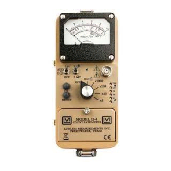
Model 12-4 Technical Manual Section 4 Section Identification of Controls and Functions : 6.4 cm (2.5 in.) arc, 1 mA analog type with pivot-and-jewel Meter suspension. Typical meter dial is 0-10 mrem/hr, 0-2.5 kV and BAT TEST Connector : Used to connect the detector to the instrument. Typically series ˝C,˝... - Page 13 Model 12-4 Technical Manual Section 4 : When depressed, this button provides a rapid means RES Pushbutton of driving the meter needle to zero. : provides meter response. Selecting the fast, ˝ ˝ position Toggle Switch of the toggle switch provides 90% of full-scale meter deflection in four seconds.
-
Page 14: Safety Considerations
Caution! The operator or responsible party is cautioned that the protection provided by the equipment may be impaired if the equipment is used in a manner not specified by Ludlum Measurements, Inc. Caution! Verify instrument voltage input rating before connecting to a power converter. -
Page 15: Cleaning And Maintenance Precautions
European Union. Cleaning and Maintenance Precautions The Model 12-4 instrument and detector may be cleaned externally with a damp cloth, using only water as the wetting agent. Do not immerse the instrument in any liquid. Observe the following precautions when cleaning or performing maintenance on the instrument: 1. -
Page 16: Calibration And Maintenance
(Discriminator) controls the amplifier gain. Equipment Required for Calibration All instruments used in calibrating the Model 12-4 must be calibrated by standards traceable to the National Institute of Standards and Technology and must have a current calibration label attached. Ludlum Measurements, Inc. -
Page 17: Initial Calibration Procedures
Model 12-4 Technical Manual Section 6 A Ludlum Model 500 Pulser or equivalent is required. If the pulser does not have an HV readout, use a high-impedance voltmeter with at least 1000 Megohm meter input resistance to adjust the detector voltage. -
Page 18: Detector Plateau
(R49) on the main board until the pointer is over the 1.5 kV mark. Place the Model 12-4 back in the can, with the unimorph speaker on the left side. Depress the Model 12-4 button and adjust the Model 12-4 HV CAL potentiometer (front panel) until the Model 12-4 meter indicates 0.5 kV. -
Page 19: Gamma Rejection
Adjust the Model 500 pulse rate to the calculated value. (Count rate should be 9600 cpm ±10%.) Set the Model 12-4 range selector switch to ×10 and adjust the ×10 calibration potentiometer for a meter reading of ˝8˝. -
Page 20: Electronic Calibration
Maintenance Instrument maintenance consists of keeping the instrument clean and periodically checking the batteries and the calibration. The Model 12-4 instrument may be cleaned with a damp cloth (using only water as the wetting agent). Do not immerse instrument in any liquid. Observe the following precautions when cleaning: 1. -
Page 21: Recalibration
Check the appropriate regulations to determine required recalibration intervals. Ludlum Measurements offers a full-service repair and calibration department. We not only repair and calibrate our own instruments, but most other manufacturers’ instruments. Calibration procedures are available upon request for customers who choose to calibrate their own instruments. -
Page 22: Troubleshooting
Note that the first troubleshooting tip is for determining whether the problem is with the electronics or with the detector. A Ludlum Model 500 Pulser is invaluable at this point, because of its ability to simultaneously check high voltage, input sensitivity or threshold, and the electronics for proper counting. - Page 23 Model 12-4 Technical Manual Section 7 SYMPTOM POSSIBLE SOLUTION No power (or meter Check battery contacts. Clean them does not reach with rough sandpaper or use an engraver to clean the tips. TEST BAT OK mark) (continued) Check for loose or broken wires, especially between the main board and the high-voltage board.
- Page 24 Model 12-4 Technical Manual Section 7 SYMPTOM POSSIBLE SOLUTION Meter goes full-scale Ensure that the instrument’s can is or “pegs out” properly attached. When attached (continued) properly, the speaker will be located on the left side of the instrument. If...
-
Page 25: Technical Theory Of Operation
Model 12-4 Technical Manual Section 8 Section Technical Theory of Operation MAIN BOARD (Drawing 464 × 275 3 sheets) Input Detector pulses are coupled through C16 to emitter follower Q4. R42 provides 3.7 V bias. R41 couples to detector HV. CR3 protects the input from high-voltage transients. -
Page 26: Scale Ranging
Model 12-4 Technical Manual Section 8 Scale Ranging Detector pulses from the discriminator are coupled to univibrator pin 5 of U9A. For each scale, the pulse width of pin 6 of U9A is increased by a factor of 10 with the actual pulse width being controlled by the front-panel calibration controls and their related capacitors. -
Page 27: Switching Convertor
Model 12-4 Technical Manual Section 8 HV Supply Board (Drawing 464 × 243) Switching Convertor HV is developed by voltage multiplier CR1 through CR10 and associated capacitors. This multiplier is driven by switching convertor U2 and T1. The convertor is powered by regulated 6 V from the main board. -
Page 28: Recycling
To this end, Ludlum Measurements, Inc. strives to supply the consumer of its goods with information regarding reuse and recycling of the many different types of materials used in its products. With many different agencies –... -
Page 29: Parts List
Model 12-4 Technical Manual Section 10 Section Parts List Reference Description Part Number Model 12-4 UNIT Completely Assembled Survey Meter Model 12 Survey Meter 48-1200 Main Board, BOARD Completely Assembled Drawing 464 × 275 Main Circuit Board 5464-275 CAPACITORS 47pF, 100V 04-5660 0.1F, 35V-T... - Page 30 Model 12-4 Technical Manual Section 10 Reference Description Part Number TRANSISTORS MMBT3904LT1 05-5841 MMBT4403LT1 05-5842 Q3-Q4 MMBT3904LT1 05-5841 VOLTAGE REGULATOR LT1460KC53-2.5 05-5867 TPS76038 05-5912 INTEGRATED CIRCUITS U1-U3 MAX4542ESA 06-6453 U4-U5 CMXT3904 05-5888 CMXT3906 05-5890 MAX4541ESA 06-6452 MAX985EUK-T 06-6459 CD74HC4538M 06-6297...
- Page 31 Model 12-4 Technical Manual Section 10 Reference Description Part Number RESISTORS R1-R5 200K, 1/8W, 1% 12-7992 8.25K, 1/8W, 1% 12-7838 10K, 1/8W, 1% 12-7839 2.37K, 1/8W, 1% 12-7861 R9-R11 10K, 1/8W, 1% 12-7839 1K, 1/4W, 1% 12-7832 10K, 1/8W, 1% 12-7839 4.75K, 1/8W, 1%...
-
Page 32: Hv Power Supply Board, Drawing 464 × 243
Model 12-4 Technical Manual Section 10 Reference Description Part Number 640456-4 - MTA100 13-8088 DET PAD-RD120 7464-270 HV PAD-RD120 7464-270 INDUCTORS 22 µH 21-9808 HV Power Supply BOARD Completely Assembled Board, Drawing HV Power Supply Board 5464-243 464 × 243 C1-C2 0.01F, 3KV, 2%... -
Page 33: Wiring Diagram, Drawing 464 × 309
Model 12-4 Technical Manual Section 10 Reference Description Part Number Wiring Diagram, MTA100×5, MAIN BOARD Drawing 464 × 309 5464-275 13-8140 CONNECTORS MTA100×6, OPTIONAL 5464-275 13-8095 MTA 100×2, MAIN BOARD 5464-275 13-8073 MTA100×4, MAIN BOARD 5464-275 13-8088 MAIN BOARD 5464-275... - Page 34 Model 12-4 Technical Manual Section 11 Section Drawings MAIN CIRCUIT BOARD, Drawing 464 × 275 (3 sheets) MAIN CIRCUIT BOARD LAYOUT, Drawing 464 × 276 (2 sheets) HV POWER SUPPLY BOARD, Drawing 464 × 243 HV POWER SUPPLY BOARD LAYOUT, Drawing 464 × 244 WIRING DIAGRAM, Drawing 464 ×...
Need help?
Do you have a question about the 12-4 and is the answer not in the manual?
Questions and answers