Table of Contents
Advertisement
Advertisement
Table of Contents

Related Manuals for LUDLUM 9DP-1


Summary of Contents for LUDLUM 9DP-1
- Page 1 LUDLUM MODEL 9DP-1 ION CHAMBER OPERATOR’S MANUAL...
- Page 3 LUDLUM MODEL 9DP-1 ION CHAMBER OPERATOR’S MANUAL December 2015 Serial Number 25002500 and Succeeding Firmware: 29307.01.01.13...
-
Page 4: Statement Of Warranty
RETURN OF GOODS TO MANUFACTURER If equipment needs to be returned to Ludlum Measurements, Inc. for repair or calibration, please send to the address below. All shipments should include documentation containing return shipping address, customer name, telephone number, description of service requested, and all other necessary information. - Page 6 Operator’s Manual MODEL 9DP-1...
- Page 7 Operator’s Manual MODEL 9DP-1...
-
Page 8: Table Of Contents
Operator’s Manual MODEL 9DP-1 Table of Contents 1. Introduction 2. Specifications 3. Control Panel 3.1 On/Off 3.2 Function 3.3 Audio 3.4 Ack/Reset 4. Display 4.1 Backlight 4.2 Startup 4.3 Instrument Information 4.4 Measurement View 4.4.1 Measurement Reading 4.4.2 Function Display 4.4.3 Status Icons... - Page 9 Operator’s Manual MODEL 9DP-1 6.1 Keyboard Controls 6.1.1 Sub Menus 6.1.2 Non-Editable Fields 6.1.3 Editable Fields 6.2 Settings 6.2.1 Product 6.2.2 Language 6.2.3 Calendar 6.2.4 Clock 6.2.5 Passwords 6.2.6 System 6.3 Controls 6.3.1 Backlight 6.3.2 Audio 6.4 Features 6.4.1 Integrate 6.4.2 Data Logging...
- Page 10 Operator’s Manual MODEL 9DP-1 10. Options 10.1 Dimension Interface Kit 10.2 Audio Jack Output 10.3 Alkaline Battery Pack 10.4 Check Source 11. Safety Considerations and Maintenance 11.1 Environmental Conditions for Normal Use 11.2 Warning Markings and Symbols 11.3 Cleaning and Maintenance Precautions 11.4 Maintenance...
-
Page 11: Introduction
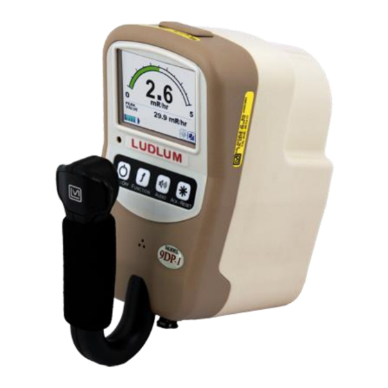
The Model 9DP-1 features a 262K-color, 320 x 240 dpi LCD that displays each measurement along with the instrument status. The LCD is backlit and automatically adjusts to the surrounding ambient condition via a built-in light sensor within the instrument. - Page 12 LCD backlighting and USB usage ranging from 12 to 30 hours. The Model 9DP-1 is equipped with a synthetically generated audible output that outputs clicks proportional to the radiation rate; however, no clicks will be heard when the meter deflection is less than 3%.
-
Page 13: Specifications
Operator’s Manual MODEL 9DP-1 Section Specifications gamma and X-rays above 25 keV; beta above 1 MeV Radiation Detected: Energy Response: ±25% from 60 keV to 1.25 MeV (see chart below) Dynamic Measurement Range: 0-500 mSv/h (0-50 R/hr, 0-500 mGy/h) : less than 1 minute when the instrument is in temperature... - Page 14 Operator’s Manual MODEL 9DP-1 (auto-ranging) Display Ranges: With Sv/h units: With R/hr units: With Gy/h units: 0-5 mR/hr 0-50 µSv/h 0-50 µGy/h 0-50 mR/hr 0-500 µSv/h 0-500 µGy/h 0-500 mR/hr 0-5 mSv/h 0-500 mGy/h 0-50 mSv/h 0-5 R/hr 0-50 mGy/h...
- Page 15 Operator’s Manual MODEL 9DP-1 per ANSI 42-17A-2003, less than 15% change in readings Ambient Pressure: from 70 kPa to 106 kPa (20.7 to 31.3 inches of mercury) : ranges from 5 seconds in the lowest range to under 2 seconds...
- Page 16 21.9 x 11.6 x 24.5 cm (8.6 x 4.6 x 9.6 in.) (H x W x L) 1.5 kg (3.3 lb), including batteries Weight: 9DP-1 % Deviation with Change in Chamber Pressure from 20 PSIG -10% 120 Pulse Xray Dose...
-
Page 17: Control Panel
Operator’s Manual MODEL 9DP-1 Section Control Panel The instrument is equipped with a four-button control pad, as shown above. All controls for the instrument are performed via these four control buttons. Each labeled button has set operation(s) it performs. The controls are as follows:... -
Page 18: On/Off
“Instrument Shutting Down,” displayed. 3.2 Function The Model 9DP-1 supports built-in functions. These functions are displayed below the main instrument rate reading. Pressing the Function button switches the function to the next available function. Each function will have a unique identifier. - Page 19 MODEL 9DP-1 This control can also be used in conjunction with resetting any functions utilizing this capability. The Model 9DP-1 incorporates the Integrate and Peak functions, both of which allow resetting their values from the button. With the desired function presented on the display, the user can press the ACK/RESET button for three seconds, after which the function value will be reset to “0.0”.
-
Page 20: Display
MODEL 9DP-1 Section Display The Ludlum Model 9DP-1 is equipped with a color LCD that improves the user’s understanding of the instrument reading, functions, and operating status, as compared to other typical display technologies. The LCD utilizes a bit-mapped layout to afford an optimized arrangement of all of the data available. -
Page 21: Startup
User Serial Number: This is an optional alpha-numeric field that can be programmed into the unit to identify a unique serial number different from the instrument serial number assigned it by Ludlum. This may be useful for tracking company inventory using the owner’s numbering system. -
Page 22: Measurement Reading
The scale is auto-ranging, meaning that as the level increases, the values noted at the start and ending points of the arc will change. Five scales exist on the Model 9DP-1 as noted in the following table. Scale Ranges SI Units – Sv/h US Units –... -
Page 23: Function Display
Operator’s Manual MODEL 9DP-1 4.4.2 Function Display The Model 9DP-1 comes pre-programmed with three functions which can be displayed. The function area is sandwiched between the measurement reading (above) and the instrument status (below). Three functions that are pre-programmed are Integrate, Peak, and Pulsed Mode. -
Page 24: Status Icons
Operator’s Manual MODEL 9DP-1 turned on and off by pressing and holding the ACK/RESET button for three seconds while the Pulsed Mode function is displayed on the screen. 4.4.3 Status Icons Several icons may be displayed across the bottom of the LCD to immediately identify the operative status of the instrument. -
Page 25: Messages
Operator’s Manual MODEL 9DP-1 Keyboard Plugged In: Icon appears when keyboard is plugged in and recognized by the instrument. Press F1 to get Menu Mode. Press ESC to get out of Menu Mode. Communication Cable: Icon appears when communication cable is initially plugged in. -
Page 26: Changing The View
USB Error Messages 4.5 Changing the View The Model 9DP-1 is programmed to only have one view. This view may, however, be exchanged for one of three other views already pre-programmed into the instrument. Exchanging views can be accomplished by connecting a standard USB keyboard to the instrument and selecting the desired view. -
Page 27: Changing The Configuration File
All correction factors and range settings listed above are the default values that can be changed by editing the configuration file. In order to change correction factor settings, the user will need the step_4 - 9DP-1 - correction factor.cfg, which is available through Ludlum Measurements. To change the correction... -
Page 28: Usb Port
MODEL 9DP-1 Section USB Port The Model 9DP-1 is equipped with one USB port that complies with the USB 2.0 standards. The port enables multiple functions for updating the instrument firmware, configuring the instrument parameters, logging data and performing setup/calibration activities. -
Page 29: Dimension File System
The file format will always have a .cfg extension. For example, the Model 9DP-1 file name might be “M9DP-1.cfg.” When the instrument attempts to load a new configuration file from the thumb drive, it will load the first file so be sure that only the new configuration file exists on the thumb drive. -
Page 30: Calibration
5.4 Calibration Complete setup and calibration capability can be accessed by connecting the instrument to a PC via Ludlum’s optional Dimension Interface Kit. This kit includes Windows® PC software, plus a special USB cable with a built-in adaptor. The Dimension Interface Kit part number is 4293-763. -
Page 31: Keyboard Menu
Operator’s Manual MODEL 9DP-1 Section Keyboard Menu A standard USB keyboard may be connected to the instrument via the USB port (with no additional USB ports, no integrated mouse or trackpad, and no sound controls). Once connected, the keyboard icon will appear on the icon display line letting the user know that the keyboard is attached and ready. -
Page 32: Non-Editable Fields
Operator’s Manual MODEL 9DP-1 6.1.2 Non-editable Fields If the selected menu line is a non-editable field, the current value for the menu item will be displayed as well as the “<-Back” menu line. Only the “<-Back” menu line may be used, which will return the user to the previous screen. -
Page 33: Settings
The field is limited to 16 characters. 6.2.2 Language “Language” can be used to select the language used by the 9DP-1; however, the only language currently supported by the 9DP-1 is English. As a result, this field is a view only field. -
Page 34: Clock
Operator’s Manual MODEL 9DP-1 “Day” represents the current calendar day and is a numeric field. Valid values for “Day” are 1 to 31. Note: When selecting the day, any value from 1 to 31 may be entered, as the instrument does not verify the day versus the number of days available in the current month;... -
Page 35: System
“System” is a sub-menu which grants access to the “Firmware Number.” Firmware Number “Firmware Number” is the current version of main firmware that the 9DP-1 is currently using and is a view-only field. This information is necessary when downloading the appropriate files from the Ludlum website should a firmware revision be required in the future. -
Page 36: Backlight
The definitions of the backlight power-up modes are: Default: pre-defined by Ludlum Measurements and is the “Auto” mode. Last: indicates that the instrument will power up in the same backlight “Operating Mode”... - Page 37 Operator’s Manual MODEL 9DP-1 Temporary: This mode automatically activates the backlight to a preset level defined by the “Always On Level” for a user-adjustable set period of time defined in “Temporary Display Time” any time a key is pressed on the keypad. The default values are 100% backlit with 10-second duration.
-
Page 38: Audio
The definitions of the backlight power-up modes are: Default: pre-defined by Ludlum Measurements and is the 40%. Last: indicates that the instrument will power up in the same audio “Operating Mode”... -
Page 39: Features
“Alarm Level” is a numeric field with valid values from 0 to 100 displayed in percentages. 6.4 Features “Features” menu allows the user to set up special capabilities of the 9DP-1. The two primary features available include the “Integrate” and the “Data Logging” features. - Page 40 Operator’s Manual MODEL 9DP-1 dose accumulation. “Delay On Power Up” is a numeric field with valid values from 1 to 180. Save On Shutdown “Save On Shutdown” represents the ability to save the current integrated dose on shut-down and use the value as the initial value the next time the instrument is powered on.
-
Page 41: Data Logging
The definitions of the data logging power-up modes are: Default: was pre-defined by Ludlum Measurements and is “Off.” Last: indicates that the instrument will power up in the same “Operating Mode”... - Page 42 Operator’s Manual MODEL 9DP-1 Operating Mode “Operating Mode” represents the current operating mode for the data logging feature. “Operating Mode” is a special field with valid values of “Off” or “On.” Delay On Power Up “Delay On Power” represents the amount of time in seconds that the instrument must wait on power-up before data logging starts logging data.
- Page 43 “Battery Voltage” is a special field with valid values of “Off” and “On.” Instrument “Instrument” is a sub-menu which grants access to the “Model,” “Ludlum Serial Number,” “User ID Number,” and “User Serial Number” settings to be reported by the data logging feature.
- Page 44 Operator’s Manual MODEL 9DP-1 Readings “Readings” is a sub-menu which grants access to the instrument readings to be reported by the data logging feature. This includes both the rate and integrated dose readings. Reading Enabling “Reading” will cause the data logging feature to report the current rate reading during normal logging events.
-
Page 45: Display
“Off” and “On.” 6.5 Display “Display” menu allows the user to set up the views associated with the 9DP-1. The 9DP-1 comes pre-configured with three views, identical in every detail with the exception of the units. -
Page 46: View 1:R/Hr
Operator’s Manual MODEL 9DP-1 Current View “Current View” represents the current operating mode for the measurement view. “Current View” is a special field with valid values of “View 1,” “View 2,” “View 3,” and “View 4.” 6.5.2 View 1: R/hr “View 1: R/hr”... - Page 47 Operator’s Manual MODEL 9DP-1 FCN 1: <function name> “FCN 1” is a sub-menu that allows access to Function 1 of the current view, including the function selected and the function enabled. “FCN 1” represents the instrument function selected for the current view.
- Page 48 Operator’s Manual MODEL 9DP-1 FCN 3: - empty – “FCN 3” is a sub-menu that allows access to Function 3 of the current view, including the function selected and the function enabled. FCN 3: <function name> “FCN 3” represents the instrument function selected for the current view.
- Page 49 Operator’s Manual MODEL 9DP-1 viewable when pressing the function key on the keypad. “FCN 4: Enable” is a special field with valid values of “On” or “Off.” Alerts “Alerts” is a sub-menu allowing access to the “Radiation” and “Integration” alerts associated with “View 1: R/hr”.
- Page 50 Operator’s Manual MODEL 9DP-1 Integration “Integration” is a sub-menu allowing access to the “Enable,” “Value,” “Multiplier,” and “Units” associated with the integration alert for View 1. If the alert is enabled, the instrument will generate an alert message and tone when the current integrated dose is equal to value represented by the “Value,”...
- Page 51 Operator’s Manual MODEL 9DP-1 Radiation “Radiation” is a sub-menu allowing access to the “Enable,” “Value,” “Multiplier,” and “Units” associated with the radiation alarm for View 1. If the alarm is enabled, the instrument will generate an alarm message and tone when the current view radiation rate is equal to value represented by the “Value,”...
-
Page 52: View 2:Sv/H
Operator’s Manual MODEL 9DP-1 Note: The error associated with displaying the integrated dose on the measurement view is one numerical unit. As a result, an alarm value of 200 uR may appear to generate an alarm when the integrated dose is between 199.9 and 200.1 uR;... -
Page 53: Functions
MODEL 9DP-1 6.6 Functions “Functions” menu allows the user to view the instrument functions associated with the 9DP-1. The 9DP-1 comes pre-configured with two functions and can be modified to include two additional functions. 6.6.1 FCN 1: Integrate “FCN 1” represents the function associated with instrument Function 1. The 9DP-1 comes pre-configured with “Integrate”... -
Page 54: Data Logging
Operator’s Manual MODEL 9DP-1 Section Data Logging The 9DP-1 is capable of logging instrument information to a file on a USB thumb drive at a pre-defined interval in a CSV (comma separate value) format. 7.1 Data Description Below is a list of all of the data that may be recorded in the log file. - Page 55 “Time” is in the format HH:MM:SS and is reported in 24- hour mode. To set the time, see Section 6.2.4. Model “Model” is a text value which indicates the model as defined by Ludlum Measurements. “Model” may contain up to 16 alpha-numeric characters. Serial Number “Serial Number”...
- Page 56 Operator’s Manual MODEL 9DP-1 Battery Voltage “Battery Voltage” is a numerical value representing the internal battery pack voltage (or the wall charger supply voltage if the wall charger is connected at the time of the reading). “Battery Voltage” is in the format X.XX.
-
Page 57: Setup
Operator’s Manual MODEL 9DP-1 Integrate Units “Integrate Units” is a text value representing the units associated with the Integrate feature. For more information, see Section 6.4.1.6.3. 7.2 Setup Perform the following steps to set up “Data Logging.” 1. Setup Logged Data To set up what data may be viewed in the data logging report, refer to Section 6.4.2.5. -
Page 58: Operation
Operator’s Manual MODEL 9DP-1 7.3 Operation Once the setup is complete, insert the thumb drive into the USB port. The thumb drive icon will appear to let the user know that the instrument has detected the thumb drive and is ready. Only when the thumb drive is detected will the instrument begin to log data. -
Page 59: Battery Power
Operator’s Manual MODEL 9DP-1 Section Battery Power The unit is powered by eight “AA” N MH (nickle-metal hydride) rechargeable batteries. Use of rechargeable batteries helps to keep operating costs down. Battery life largely depends upon the LCD backlighting and USB port usage, resulting in a range spanning between 12 to 30 hours. - Page 60 Operator’s Manual MODEL 9DP-1 The power charger input accommodates 108-240 V at between 50/60 Hz. The output is 15.0 V at 1600 mA. To ensure proper charging, do not use chargers with other specifications than those listed above. Charging circuitry to monitor battery levels and protect the NiMH batteries from over-charging is all built into the Ludlum instrument.
-
Page 61: Battery Installation
Operator’s Manual MODEL 9DP-1 8.1 Battery Installation 1. Find the battery access door located at the bottom of the Dimension Portable Series instrument. 2. The battery cover is held on by a single screw. Give the screw a quarter of a turn with a screwdriver, and the door will pop up. - Page 62 Operator’s Manual MODEL 9DP-1 depletes, each succeeding cell beginning on the right going left, changes its color from green to the screen background color, signifying it has emptied. When only two cells remain (40% of battery life), they both turn to yellow to warn the user that time is getting short.
-
Page 63: Battery Pack Removal
MODEL 9DP-1 8.3 Battery Pack Removal When removing the battery pack on the Ludlum Model 9DP, be careful to lift the battery pack from the rear (the end opposite the contacts). Lifting the battery pack from the side can cause a short circuit and a large current to flow from the battery pack. -
Page 64: Operational Test
This is an exempt quantity in the USA so no license is required to purchase and receive this source. You can purchase it from Ludlum by ordering Part Number 01-5231. Several other countries only permit 0.25 µCi Cs as an exempt status, so check your local regulations. -
Page 65: Options
Part Number: 4293-763 10.2 Audio Jack Output The Model 9DP-1 provides an audio output via its built-in speaker. An optional audio jack can be purchased to facilitate connection to an audio headset. This option works well whenever the ambient noise levels are too loud or when radioactive clicking sounds may not be desired, such as in an office type environment. -
Page 66: Alkaline Battery Pack
Note: Ludlum also offers a 0.25 µCi Cs source for countries with lower exempt criteria. This can be purchased under Part Number: 01-5723. Note: Ludlum also offers other sources. Please contact us, one of our representatives, or visit www.ludlums.com for more information. -
Page 67: Safety Considerations And Maintenance
The operator or responsible body is cautioned that the protection provided by the equipment may be impaired if the equipment is used in a manner not specified by Ludlum Measurements, Inc.The Model 9DP-1 Ion Chamber is marked with the following symbols: CAUTION (per ISO 3864, No. -
Page 68: Cleaning And Maintenance Precautions
11.3 Cleaning and Maintenance Precautions Instrument maintenance consists of keeping the instrument clean and periodically checking the batteries and calibration. The Model 9DP-1 may be cleaned externally with a damp cloth, using only water as the wetting agent. Do not immerse the instrument in any liquid. Observe the following precautions when cleaning or performing maintenance on the instrument: 1. -
Page 69: Maintenance
Check the appropriate regulations to determine required recalibration intervals. Ludlum Measurements offers a full-service repair and calibration department. We not only repair and calibrate our own instruments, but also most other manufacturers’ instruments. Calibration procedures are available upon request for customers who choose to calibrate their own instruments. - Page 70 Every returned instrument must be accompanied by an Instrument Return Form, which can be downloaded from the Ludlum website at www.ludlums.com. Find the form by clicking the “Support” tab and selecting “Repair and Calibration” from the drop-down menu. Then choose the appropriate Repair and Calibration division where you will find a link to the form.
-
Page 71: Certificate Of Compliance
Operator’s Manual MODEL 9DP-1 Section Ludlum Measurements, Inc. December 2015... -
Page 72: Recycling
To this end, Ludlum Measurements, Inc. strives to supply the consumer of its goods with information regarding reuse and recycling of the many different types of materials used in its products.
Need help?
Do you have a question about the 9DP-1 and is the answer not in the manual?
Questions and answers