
Related Manuals for LUDLUM 177-56


Summary of Contents for LUDLUM 177-56
- Page 1 LUDLUM MODEL 177-56 RATEMETER January 2019 Serial Number 322945 and Succeeding Serial Numbers...
- Page 2 LUDLUM MODEL 177-56 RATEMETER January 2019 Serial Number 322945 and Succeeding Serial Numbers...
- Page 3 RETURN OF GOODS TO MANUFACTURER If equipment needs to be returned to Ludlum Measurements, Inc. for repair or calibration, please send to the address below. All shipments should include documentation containing return shipping address, customer name, telephone number, description of service requested, and all other necessary information.
-
Page 6: Table Of Contents
Model 177-56 Technical Manual Table of Contents Introduction Getting Started Unpacking and Repacking Preparing the Instrument for Use Operating the Instrument Specifications Description of Controls and Functions Front Panel Back Panel CAL Control - Alpha Internal Controls (Overhaul Only) CAL Control – Beta... - Page 7 High Voltage (HV) Low Voltage Battery Charge High Voltage Test Battery Test Voltage Recycling Parts List Model 177-56 Ratemeter 10-1 Main Board, Drawing 347 × 603 10-1 Calibration Board, Drawing 347 × 132 10-4 Power/Data Board, Drawing 347 x 489...
-
Page 8: Introduction
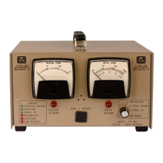
Model 177-56 Technical Manual Section 1 Section Introduction he Ludlum Model 177-56 is a dual-detector (scintillator/GM) system, allowing selection of either alpha or beta readings, functioning as an alpha/beta frisking station. Note: There is no ALARM audio on this system. -
Page 9: Getting Started
Check individual item serial numbers and ensure calibration certificates match between instruments and detectors (if applicable). The Model 177-56 serial number is located on the back panel of the instrument. To return an instrument for repair or calibration, provide sufficient packing material to prevent damage during shipment. -
Page 10: Operating The Instrument
Model 177-56 Technical Manual Section 2 single operating point). Expose the detector to a source and increase the voltage until a stable reading is obtained from the source. Connect the instrument to line power, and then turn the power switch to ON. -
Page 11: Specifications
Model 177-56 Technical Manual Section 3 Section Specifications 95-250 VAC wall transformer and 6-volt gel-cell (sealed lead-acid) Power: battery; typical battery life of approximately 50 hours with a fully charged battery. 1 amp 3AG fuse Fuse: toggle switch control selects FAST (2.2 seconds) or... - Page 12 Model 177-56 Technical Manual Section 3 may be used to externally add to or subtract from the Unbuffered Output: meter reading powder coat paint Finish: 16 x 20.3 x 17.5 cm (6.3 x 8 x 6.9 in.) (H x W x D), excluding handle Size: 1.9 kg (4.2 lb) with battery...
-
Page 13: Description Of Controls And Functions
Model 177-56 Technical Manual Section 4 Section Description of Controls and Functions Front Panel provides 9 VDC through a wall transformer to Power ON-OFF Switch: the instrument and trickle-charges the standby battery. In case of line power failure, the battery automatically comes online to power the instrument. -
Page 14: Back Panel
Model 177-56 Technical Manual Section 4 The beta/GM detector is a series C connector. The alpha/ Connectors: scintillator is an MHV connector. This button, when depressed, provides a rapid means of RESET Button: driving the meter needle to zero. When in the... -
Page 15: Cal Control - Alpha
Discrimination control. Alpha scintillator side, adjust the DISCR: discriminator to 10 ± 2 millivolts. This control has an adjustable range of 10 to 100 millivolts. A Ludlum Model 500 Pulser may be used to determine the discrimination level. X1000 through X1 calibration controls used to Calibration Controls: calibrate each of the ranges. -
Page 16: Internal Controls (Overhaul Only)
The discrimination level on the pancake board (-595) is Pancake DISC: fixed at around 10 mV and can be checked with a Ludlum m500 pulser. Apply an -80mV signal to the C connector on the front panel to test. Note: Approaching -10 mV, the trip point can cause oscillation and will yield count errors. -
Page 17: Safety Considerations
Cleaning Instructions and Precautions The Model 177-56 Ratemeter may be cleaned externally with a damp cloth, using only water as the wetting agent. Do not immerse the instrument in any liquid. Observe the following precautions when cleaning: 1. -
Page 18: Warning Markings And Symbols
Caution! The operator or responsible body is cautioned that the protection provided by the equipment may be impaired if the equipment is used in a manner not specified by Ludlum Measurements, Inc. Caution! Verify instrument voltage input rating before connecting to a power converter. - Page 19 Doing so may result in the unit falling down and causing personal injury and/or property damage. The Model 177-56 Ratemeter is marked with the following symbols: CAUTION (per ISO 3864, No. B.3.1) – designates hazardous live voltage and risk of electric shock.
-
Page 20: Calibration And Maintenance
Note: Local procedures may supersede the following. In order to calibrate both the ratemeter and HV, the user will need a Ludlum Model 500 pulser or equivalent and a high–impedance voltmeter with at least 1000 Megohm meter input resistance to adjust the detector voltage. -
Page 21: Establishing An Operating Point
Model 177-56 Technical Manual Section 6 Establishing a Detector Operating Point: The operating point for the instrument and detectors is established by setting the detector voltage and instrument sensitivity ( ). The proper selection of this point is the key to instrument performance. -
Page 22: Maintenance
Recalibration should be accomplished after any maintenance or adjustment has been performed on the instrument. Ludlum Measurements recommends recalibration at intervals no greater than one year. Local regulations may have precedence over this recommendation. -
Page 23: Troubleshooting
Note that the first troubleshooting tip is for determining whether the problem is with the electronics or with the detector. A Ludlum Model 500 Pulser is invaluable at this point because of its ability to simultaneously check high voltage, input sensitivity or threshold, and the electronics for proper counting. -
Page 24: Troubleshooting Gm Detectors
Model 177-56 Technical Manual Section 7 SYMPTOM POSSIBLE SOLUTION Non-linear Readings Check the high voltage (HV) by pressing the button. If a HV TEST multimeter is used to check the HV, ensure that one with high impedance is used; as a standard multimeter could be damaged in this process. -
Page 25: Troubleshooting Scintillators
Technical Manual Section 7 2. Check the HV. For most GM tubes, the voltage is normally 900 VDC, or 460-550 VDC for “peanut” tubes (Ludlum Model 133 series). 3. If the input sensitivity is too low, the user could see some double-pulsing. -
Page 26: Technical Theory Of Operation
Model 177-56 Technical Manual Section 8 Section Technical Theory of Operation Amplifier Negative detector pulses are coupled through C124 to emitter follower Pin U121. R127 protects the input from inadvertent high-voltage shorts. R129 couples the detector to the high-voltage supply. -
Page 27: Time Constant
Model 177-56 Technical Manual Section 8 discharged by R124. The average voltage on C122 is coupled through switch to voltage-follower Pin 5 of U311. Pin 7 of U311 drives the meter and recorder output. Time Constant The meter time constant is determined by R124 and C122. For a slower time constant, C122 is paralleled by C101. -
Page 28: Battery Charge
Model 177-56 Technical Manual Section 8 Battery Charge Battery charge is provided by voltage regulator U201 and power transistor Q301. R402 limits charge current for discharged battery. A negative voltage coefficient of -0.0063 volts per degree F is provided by ratio of R013/R201. -
Page 29: Recycling
To this end, Ludlum Measurements, Inc. strives to supply the consumer of its goods with information regarding reuse and recycling of the many different types of materials used in its products. With many different agencies –... -
Page 30: Parts List
Model 177-56 Technical Manual Section 10 Section Parts List Reference Description Part Number Model 177-56 UNIT Completely Assembled Ratemeter Model 177 Ratemeter 48-1323 Main Board, Drawing BOARD Completely Assembled 347 × 603 Circuit Board 5347-603 CAPACITORS C001 10µF, 25V, 04-5655... - Page 31 Model 177-56 Technical Manual Section 10 Reference Description Part Number C401-C402 1µF, 35V 04-5656 C403 0.1µF, 50V 04-5663 C411 47µF, 16V 04-5666 C421 0.0047µF, 3KV 04-5958 C422 0.0047UF, 3KV 04-5547 C423 0.0047µF, 3KV 04-5958 TRANSISTORS Q104 MMBT3904T1G 05-5841 Q111 MMBT3904T1G...
- Page 32 Model 177-56 Technical Manual Section 10 Reference Description Part Number RESISTORS R014-R015 100K, 1%, 250mW 12-7834 R016 100Ohm, 1%, 250mW 12-7840 R017 100K, 1%, 250mW 12-7834 R018 150Ohm, 1%, 250 mW 12-7062 R019 56.2K, 1%, 250 mW 12-7873 R020 100K, 1%, 250mW...
-
Page 33: Calibration Board, Drawing 347 × 132
Model 177-56 Technical Manual Section 10 Reference Description Part Number R302 1.00K, 1%, 250mW 12-7832 R303 2.21K, 1%, 250mW 12-7835 R311 750K, 1%, 250mW 12-7882 R312 301 ohm, 1%, 250mW 12-7863 R313 475 ohm, 1%, 250mW 12-7851 R315 22.1K, 1%, 250mW... - Page 34 Model 177-56 Technical Manual Section 10 Reference Description Part Number RESISTOR 680, 1/3W 12-7885 RESISTOR NETWORK 12-7720 MISCELLANEOUS CONN 1-640457-1 MTA100 13 8397 Power/Data Board, BOARD Completely Assembled 5347-489 Drawing 347 × 489 Power/Data Board 1N5817 07-6290 DIODE RESISTOR 150Ohm, 5%, 250mW...
- Page 35 Model 177-56 Technical Manual Section 10 Reference Description Part Number LM1815 06-6937 INTEGRATED CIRCUITS LT1304CS8 06-6394 TLV2333 06-6980 SN74AHC1G14DBVR 06-6556 SN74LVC1G07DBVR 06-7033 TPS76050DBVR 05-5913 MBR0520LT1G 07-6422 DIODES CR2-CR7 CMPD2004S 07-6402 RESISTORS 100K, 1%, 100mW 12-7082 21.5K, 1%, 250mW 12-7001 R3-R5...
- Page 36 Model 177-56 Technical Manual Section 10 30-1 PB (RESET) 08-6517 M2012SS1W01-RO (DETECTOR) 08-6511 POTENTIOMETERS 10K, VOLUME 09-6753 CONNECTORS MAIN BOARD 5347-603, (CONN 640428-3 MTA 156X3) 13-8124 PANCAKE BOARD 5347-595, (CONN 640445-3 MTA 156X3) 13-8125 MAIN BOARD 5347-603, (CONN 1-640441-2 MTA 100X12)
-
Page 37: Power/Data Board, Drawing 347 X 489
Model 177-56 Technical Manual Section 11 Section Drawings MAIN BOARD, Drawing 347 × 603 (4 sheets) MAIN BOARD Component Layout, Drawing 347 × 604 (2 sheets) CALIBRATION BOARD, Drawing 347 × 132 CALIBRATION BOARD Component Layout, Drawing 347 × 133...
Need help?
Do you have a question about the 177-56 and is the answer not in the manual?
Questions and answers