
Subscribe to Our Youtube Channel
Related Manuals for LUDLUM MODEL 3


Summary of Contents for LUDLUM MODEL 3
- Page 1 LUDLUM MODEL 3 SURVEY METER April 2016 Serial Number 294605 and Succeeding Serial Numbers...
- Page 2 LUDLUM MODEL 3 SURVEY METER April 2016 Serial Number 294605 and Succeeding Serial Numbers...
-
Page 3: Statement Of Warranty
RETURN OF GOODS TO MANUFACTURER If equipment needs to be returned to Ludlum Measurements, Inc. for repair or calibration, please send to the address below. All shipments should include documentation containing return shipping address, customer name, telephone number, description of service requested, and all other necessary information. -
Page 5: Table Of Contents
Cleaning and Maintenance Precautions Calibration and Maintenance Calibration Exposure Rate Calibration CPM Calibration Establishing an Operating Point Maintenance Recalibration Batteries Troubleshooting Troubleshooting Electronics which utilize a GM Detector or Scintillator Troubleshooting GM Detectors Troubleshooting Scintillators Ludlum Measurements, Inc. April 2016... - Page 6 Discriminator Audio Scale Ranging Meter Drive Meter Reset Fast/Slow Time Constant Recycling Parts List Model 3 Survey Meter 10-1 Main Board, Drawing 464 × 204 10-1 Wiring Diagram, Drawing 464 × 212 10-3 Drawings and Diagrams Ludlum Measurements, Inc. April 2016...
-
Page 7: Introduction
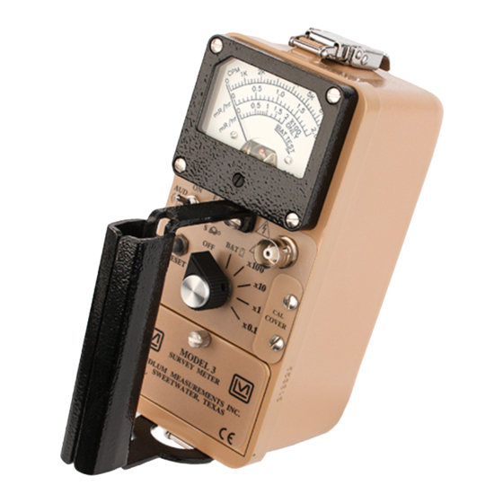
Section 1 Section Introduction he Model 3 is a portable radiation survey instrument with four linear ranges used with exposure rate or cpm (counts per minute) meter dials, or a combination of both exposure rate and count rate (referred to as “combo”) meter face dials. The instrument features a... -
Page 8: Getting Started
The Model 3 serial number is located on the front panel below the battery compartment. Most Ludlum Measurements, Inc. detectors have a label on the base or body of the detector for model and serial number identification. -
Page 9: Connecting A Detector To The Instrument
A mild electric shock may occur if you make contact with the center pin of the input connector. Switch the Model 3 range selector switch to the position before connecting or disconnecting the cable or detector. -
Page 10: Reading The Meter Face Dial
Model 3 Technical Manual Section 2 The detector cable can be a source of problems. Test the detector cable by bending or flexing either end of the cable and checking for an increase of counts detected. Replace the cable if increases in the rate of counts are detected. - Page 11 Model 3 Technical Manual Section 2 The same needle indications on successive ranges would be: ×1 = 3.5 kcpm (or 3500 cpm) ×10 = 35 kcpm (or 35,000 cpm) ×100 = 350 kcpm (or 350,000 cpm) A typical dual scale (two arcs) meter face is shown below. The top scale reads 0-2 mR/hr.
- Page 12 1.0 mR/hr mark on the middle arc lines up with 3.3 kcpm on the upper arc. The meter face in this example works with a detector that receives 3.3 kcpm per mR/hr (the Ludlum Model 44-9 pancake detector.) In the following picture, the needle is on the first tick mark past the 4 kcpm mark.
-
Page 13: Operational Check
Model 3 Technical Manual Section 2 The same needle indications on successive ranges would be: ×1 = 4.2 kcpm (or 4200 cpm) ×10 = 42 kcpm (or 42,000 cpm) ×100 = 420 kcpm (or 420,000 cpm) If you use the mR/hr scales, then the readings would be: ×0.1 = 0.13 mR/hr... -
Page 14: Specifications
Model 3 Technical Manual Section 3 Section Specifications : adjustable from 400 to 1500 Vdc High Voltage Threshold : fixed at -35 mV ± 10 mV : toggle switch for fast (4 seconds) or slow (22 seconds) from 10% Response... - Page 15 Model 3 Technical Manual Section 3 : 16.5 x 8.9 x 21.6 cm (6.5 x 3.5 x 8.5 in.) (H x W x L), including handle Size : 1.6 kg (3.5 lb), including batteries Weight Construction : cast and drawn aluminum with beige powder coat Ludlum Measurements, Inc.
-
Page 16: Identification Of Controls And Functions
Technical Manual Section 4 Section Identification of Controls and Functions See the Model 3 FRONT PANEL drawing at the beginning of this manual to reference the following controls: : 6.4 cm (2.5 in.) arc, 1 mA analog type with pivot-and-jewel Meter suspension. - Page 17 Model 3 Technical Manual Section 4 the higher the audio frequency. The audio should be turned when not required, in order to reduce battery drain. Note: A low-battery condition results in a steady audio tone, regardless of the position of the AUD ON-OFF switch.
-
Page 18: Safety Considerations
Caution! The operator or responsible body is cautioned that the protection provided by the equipment may be impaired if the equipment is used in a manner not specified by Ludlum Measurements, Inc. Caution! Verify the instrument voltage input rating before connecting to a power converter. -
Page 19: Cleaning And Maintenance Precautions
European Union. Cleaning and Maintenance Precautions The Model 3 may be cleaned externally with a damp cloth, using only water as the wetting agent. Do not immerse the instrument in any liquid. Observe the following precautions when cleaning or performing maintenance on the instrument: 1. -
Page 20: Calibration And Maintenance
Model 3 Technical Manual Section 6 Section Calibration and Maintenance Calibration Calibration controls are located on the front of the instrument under the calibration cover. The controls may be adjusted with a 0.32 cm (one- eighth inch) blade screwdriver. Note: Local procedures may supersede the following. -
Page 21: Exposure Rate Calibration
400 µR/hr point. Then switch the pulser multiplier switch to the next lower setting, and adjust the appropriate calibration control on the Model 3 for the meter to read 40 µR/hr. -
Page 22: Cpm Calibration
Check the 20% scale indication of the Model 3 by reducing the pulser count rate by a factor of 4. The Model 3 should read within 10% of the actual pulse rate. Decrease the pulse rate of the Model 500 by one decade and turn the Model 3 range selector to the next lower range. -
Page 23: Establishing An Operating Point
The system gain is controlled by adjusting the high voltage. Note: Measure the high voltage with a Ludlum Model 500 Pulser. If the pulser does not have a high-voltage readout, use a high- impedance voltmeter with at least 1000 megohm input resistance to measure the high voltage. -
Page 24: Maintenance
Maintenance Instrument maintenance consists of keeping the instrument clean and periodically checking the batteries and the calibration. The Model 3 instrument may be cleaned with a damp cloth (using only water as the wetting agent). Do not immerse instrument in any liquid. Observe the following precautions when cleaning: 1. -
Page 25: Batteries
Check the appropriate regulations to determine required recalibration intervals. Ludlum Measurements offers a full-service repair and calibration department. We not only repair and calibrate our own instruments, but most other manufacturer’s instruments as well. Calibration procedures are available upon request for customers who choose to calibrate their own instruments. -
Page 26: Troubleshooting
(3) battery contacts. Note that the first troubleshooting tip is for determining whether the problem is with the electronics or with the detector. A Ludlum Model 500 Pulser is invaluable at this point, because of its ability to simultaneously check high voltage, input sensitivity or threshold, and the electronics for proper counting. - Page 27 Remove the can and check for loose or broken wires. Check the high voltage ( ) using a nonlinear readings Ludlum Model 500 Pulser (or equivalent). If a multimeter is used to check the , ensure that one with high impedance is used, as a standard multimeter could be damaged in this process.
-
Page 28: Troubleshooting Gm Detectors
1. If the tube has a thin mica window, check for window breakage. If damage is evident, the tube must be replaced. 2. Check the . For most GM tubes, the voltage is normally 900 Vdc, or 460-550 Vdc for “peanut” tubes (Ludlum Model 133 series). Ludlum Measurements, Inc. Page 7-3... -
Page 29: Troubleshooting Scintillators
Model 3 Technical Manual Section 7 3. If the input sensitivity is too low, the user could see some double-pulsing (where the instrument “counts” a single pulse from the detector multiple times). 4. Wires to the tube may be broken, or the crimped connector could have a loose wire. -
Page 30: Technical Theory Of Operation
Model 3 Technical Manual Section 8 Section Technical Theory of Operation Low-Voltage Supply Battery voltage is coupled to U11 and associated components (a switching regulator) to provide 5 volts at pin 8 to power all logic circuits. A voltage divider (R27 and R32) located at pin 1 of U11 sets the end-of-battery–life squeal at 2.0 Vdc. -
Page 31: Discriminator
Model 3 Technical Manual Section 8 Discriminator Comparator U8 provides discrimination. The discriminator is set by a voltage divider (R21 and R23), coupled to pin 3 of U8. As the amplified pulses at pin 4 of U8 increase above the discriminator voltage, 5-volt negative pulses are produced at pin 1 of U8. -
Page 32: Recycling
To this end, Ludlum Measurements, Inc. strives to supply the consumer of its goods with information regarding reuse and recycling of the many different types of materials used in its products. With many different agencies –... -
Page 33: Parts List
Technical Manual Section 10 Section Parts List Reference Description Part Number Model 3 UNIT Completely Assembled Survey Meter Model 3 Survey Meter 48-1605 Main Board, BOARD Completely Assembled Drawing 464 × 204 Main Circuit Board 5464-204 CAPACITORS 47pF, 100V 04-5660 0.1F, 35V... - Page 34 Model 3 Technical Manual Section 10 Reference Description Part Number TRANSISTORS MMBT3904LT1 05-5841 MMBT4403LT1 05-5842 INTEGRATED CIRCUITS U1-U3 MAX4542ESA 06-6453 U4-U5 CMXT3904 05-5888 CMXT3906 05-5890 MAX4541ESA 06-6452 MAX985EUK-T 06-6459 CD74HC4538M 06-6297 LMC7111BIM5X 06-6410 LT1304CS8-5 06-6434 MIC1557BM5 06-6457 LT1304CS8 06-6394 DIODES...
-
Page 35: Wiring Diagram, Drawing 464 × 212
Model 3 Technical Manual Section 10 Reference Description Part Number 200K, 1/8W, 1% 12-7992 10K, 1/8W, 1% 12-7839 1K, 1/8W, 1% 12-7832 4.75K, 1/8W, 1% 12-7858 2K, 1/8W, 1% 12-7926 R20-R21 100K, 1/8W, 1% 12-7834 1M, 1/8W, 1% 12-7844 2.49K, 1/8W, 1% 12-7999 14.7K, 1/8W, 1%... - Page 36 ˝D˝ DURACELL BATTERY 21-9313 MISCELLANEOUS PORTABLE BATTERY NEGATIVE CONTACT ASSEMBLY 2001-065 PORTABLE BATTERY POSITIVE CONTACT ASSEMBLY 2001-066 MODEL 3 CASTING 7464-219 MODEL 3 MAIN HOUSING 8464-035 PORTABLE CAN ASSEMBLY (MTA) 4363-441 PORTABLE KNOB 08-6613 METER ASSEMBLY METER BEZEL W/GLASS W/O SCREWS 4363-188...
-
Page 37: Drawings And Diagrams
Model 3 Technical Manual Section 11 Section Drawings and Diagrams MAIN CIRCUIT BOARD, Drawing 464 × 204 (3 sheets) MAIN CIRCUIT BOARD LAYOUT, Drawing 464 × 205 (2 sheets) CHASSIS WIRING DIAGRAM, Drawing 464 × 212 Ludlum Measurements, Inc. Page 11-1...
Need help?
Do you have a question about the MODEL 3 and is the answer not in the manual?
Questions and answers