
Related Manuals for LUDLUM 177-84-1


Summary of Contents for LUDLUM 177-84-1
- Page 1 LUDLUM MODEL 177-84-1 ALPHA/BETA RATEMETER Addendum to Model 177-84 Manual April 2018 Serial Number 128600 and Succeeding Serial Numbers...
- Page 2 LUDLUM MODEL 177-84-1 ALPHA/BETA RATEMETER Addendum to Model 177-84 Manual April 2018 Serial Number 128600 and Succeeding Serial Numbers...
- Page 4 Model 177-84 manual September 2014 The Model 177-84-1 is similar to the Model 177-84 with the following changes: 1. The mode selector switch was moved to the back. 2. The LEDs for “OK” and “INCOMPLETE” were deleted from the front panel.
- Page 5 RETURN OF GOODS TO MANUFACTURER If equipment needs to be returned to Ludlum Measurements, Inc. for repair or calibration, please send to the address below. All shipments should include documentation containing return shipping address, customer name, telephone number, description of service requested, and all other necessary information.
-
Page 9: Table Of Contents
Table of Contents 1. INTRODUCTION ............................ 1 2. SPECIFICATIONS ........................... 3 3. DESCRIPTION OF CONTROLS AND FUNCTIONS ................5 ............................5 RONT ANEL ............................. 6 ANEL ..........................6 NTERNAL ONTROLS 4. SAFETY CONSIDERATIONS AND MAINTENANCE ................ 9 ................. 9 NVIRONTMENTAL ONDITIONS FOR ORMAL .................. -
Page 11: Introduction
Diodes) located underneath the meters. A regulated high-voltage power supply adjustable from 200 to 2000 volts with detector overload detection is utilized to operate a wide range of scintillation detectors. Other operating features of the instrument include Ludlum Measurements, Inc. Page 1 April 2018... - Page 12 The unit operates on line power or an internal rechargeable battery. It is useable in temperatures ranging from -15 to approximately 50 °C (5 to 122 Ludlum Measurements, Inc. Page 2 April 2018...
-
Page 13: Specifications
AUDIO: Dual tone click-per-event through a built-in unimorph with an internal volume control and internally switchable divide by of 1, 10, 100, and 1000 counts per click (beta only). ALARM RANGE: adjustable from 0 through full scale FINISH: powder coat paint Ludlum Measurements, Inc. Page 3 April 2018... - Page 14 BATTERY DEPENDANCE: instrument calibration change less than 3% until Low Battery LED comes on SIZE: 19.1 x 22.9 x 15.3 cm (7.5 x 9 x 6 in.) (H x W x L), excluding handle WEIGHT: 2.3 kg (4.9 lb) Ludlum Measurements, Inc. Page 4 April 2018...
-
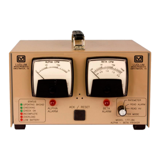
Page 15: Description Of Controls And Functions
LED is illuminated. LOW BATTERY: This LED will come on when the charge on the battery has dropped below the useable range. The voltage level is 5.5 volts measured at the battery terminals. Ludlum Measurements, Inc. Page 5 April 2018... -
Page 16: Rear Panel
METER MODE switch to READ ALARM in order to view and set the alarm point. The alarm point can be set from zero to full scale. AMC - Alpha Meter Cal: This control calibrates the Alpha meter. Ludlum Measurements, Inc. Page 6 April 2018... - Page 17 Example: For a setting of 1000, the instrument will give one click for every 1000 counts it registers. Note: The AUDIO divide function only affects the lower frequency beta tones. The higher frequency clicks-per-events will be unaffected by the divide-by selection. Ludlum Measurements, Inc. Page 7 April 2018...
- Page 18 The duration of the counting period for different settings is listed below: Setting Duration until switch opened 8 seconds 16 seconds 24 seconds 32 seconds 112 seconds 120 seconds Ludlum Measurements, Inc. Page 8 April 2018...
-
Page 19: Safety Considerations And Maintenance
Observe the following precautions when cleaning 1. Turn the instrument OFF and disconnect the instrument power cord. 2. Allow the instrument to sit for one minute before cleaning. Ludlum Measurements, Inc. Page 9 April 2018... -
Page 20: Replacement Of Fuses
To return an instrument for repair or calibration, provide sufficient packing material to prevent damage during shipment. Every returned instrument must be accompanied by an Instrument Return Form, which can be downloaded from the Ludlum website at Ludlum Measurements, Inc. Page 10... -
Page 21: Battery Replacement
Avoid installing or mounting the unit or its power supply in unstable locations, such as on a rickety table or a slanted surface. Doing so may result in the unit falling down and causing personal injury or property damage. Ludlum Measurements, Inc. Page 11 April 2018... -
Page 22: Operating Procedures
Connect a Ludlum Model 500 Pulser or equivalent to the Model 177-84. While the Model 177-84 is in the Updating Background mode, adjust the beta threshold (BT) for 2.0 mV and the window (BW) for 50 mV. The pulser counts should be detected on the beta meter above 2.0 ±1 mV... -
Page 23: Theory Of Operation
1, 2, and 3 of U021. R202, Beta Window (defined as the upper threshold limit of the beta counting window) provides the reference voltage for the beta window comparator pins 5, 6, and 7 of U021. Ludlum Measurements, Inc. Page 13 April 2018... -
Page 24: Alpha/Beta Discriminator Logic Circuit
A voltage drop is developed across R131 and sensed by comparator U022 as detector current increases. When the voltage at pin 3 of U022 goes below pin 2, pin 1 goes low, illuminating the OVERLOAD LED and driving the Ludlum Measurements, Inc. Page 14 April 2018... -
Page 25: Meter Drive
Alpha and/or beta audio pulse frequency is generated by the µP and coupled to Q501. Q501 then inverts the pulses and drives the negative side of the speaker. Bias voltage is provided by the volume control, R402. Ludlum Measurements, Inc. Page 15 April 2018... -
Page 26: Recycling
To this end, Ludlum Measurements, Inc. strives to supply the consumer of its goods with information regarding reuse and recycling of the many different types of materials used in its products. -
Page 27: Parts List
04-5664 C322 1 UF, 35V 04-5656 C421 0.1UF, 50V 04-5663 C422 1 UF, 35V 04-5656 C423 10 UF, 20V 04-5655 C424-C431 68 UF, 6.3V 04-5654 C432 2700MF, 35V 04-5621 C511 47MF, 10V 04-5666 Ludlum Measurements, Inc. Page 17 April 2018... - Page 28 1.5K 1/8W 1% 12-7878 R103 10K TRIMMER 09-6931 R104 100K TRIMMER 09-6930 R111 100K 1/8W 1% 12-7834 R112 100K 1/8W 1% 12-7834 R121 100 OHM 1/8W 1% 12-7840 R122 100K 1/8W 1% 12-7834 Ludlum Measurements, Inc. Page 18 April 2018...
- Page 29 10K 1/8W 1% 12-7839 R511 22.1K 1/8W 1% 12-7843 R512 24.3K 1/8W 1% 12-7867 R521 22.1K 1/8W 1% 12-7843 R522 1K 1/8W 1% 12-7832 R523 165K 1/8W 1% 12-7877 R524 2.2 OHM 1/8W 5% 12-7932 Ludlum Measurements, Inc. Page 19 April 2018...
-
Page 30: Front Panel Board, Drawing 347 X 244
5347-316 C110 100µF, 35V 04-5595 CAPACITORS DS113 LED-E112 07-6390 LEDS DS114 LED-E112 07-6390 DS115 LED-E112 07-6390 DS116 LED-E116 07-6393 DS117 LED-E116 07-6393 DS118 LED-E116 07-6393 DS119 LED-E176 RED 07-6362 DS120 LED-E176 RED 07-6362 Ludlum Measurements, Inc. Page 20 April 2018... -
Page 31: Chassis Wiring Diagram, Drawing 347 X 243
MAIN BOARD MODEL 177-84 5347-314 FRONT PANEL BOARD 5347-316 Model 177-84 FRONT CHASSIS HARNESS Model 177-84 8347-327 REAR CHASSIS HARNESS MODEL 177-84 8347-323 BATTERY NP1-6 YUASA 21-9385 FUSE 1 AMP 5X20mm 21-9704 TRANSFORMER 22-9908 Ludlum Measurements, Inc. Page 21 April 2018... -
Page 32: Appendix
Turn the instrument OFF, and move dipswitch #3 to the OFF position. 5. Connect the instrument to a Ludlum Model 500 pulser set at 60 mV pulse height and 100 cpm. Rotate the pots labeled AAP (Alpha Alarm Point), BAP (Beta Alarm Point), and OL (OverLoad) fully clockwise. - Page 33 LED with the second press. Switch dipswitch #4 to OFF to put the instrument into non-latching alarm mode and verify that the alarm is non-latching. Ludlum Measurements, Inc. Page 23 April 2018...
-
Page 34: Appendix 2: Model 177-84 Mode Switch Addition
Mechanically, the toggle switch and a silkscreened plate is mounted on the front of the instrument. The part number for the Mode Switch Addition is 4347-366. Ludlum Measurements, Inc. Page 24 April 2018... -
Page 35: Appendix 3: Model 4902 Specifications
Model 4902. If a count timer is required, the instrument used with the Model 4902 must have that capability. An instrument typically used with the Model 4902 is a Ludlum Model 177-84. Other instruments can be used. -
Page 36: Drawings And Diagrams
Main Board Component Layout, Drawing 347 x 243A (2 sheets) Front Panel Board, Drawing 347 x 244 Front Panel Board Component Layout, Drawing 347 x 258A (2 sheets) Wiring Diagram, Drawing 347 x 243 Ludlum Measurements, Inc. Page 26 April 2018...
Need help?
Do you have a question about the 177-84-1 and is the answer not in the manual?
Questions and answers