DAVIS vantage pro2 groweather User Manual
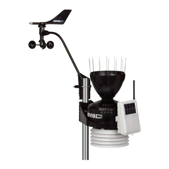
Integrated sensor suite with solar radiation sensor & 24-hour fan
Hide thumbs
Also See for vantage pro2 groweather:
- User manual ,
- Console manual (56 pages) ,
- Manual (56 pages)
Table of Contents
Troubleshooting

Related Manuals for DAVIS vantage pro2 groweather


Summary of Contents for DAVIS vantage pro2 groweather
- Page 1 USER MANUAL ™ Vantage Pro2 GroWeather Integrated Sensor Suite with Solar Radiation Sensor & 24-Hour Fan Product numbers 6825 and 6825C Davis Instruments, 3465 Diablo Avenue, Hayward, CA 94545-2778 U.S.A. • 510-732-9229 • www.davisnet.com...
- Page 2 The new cone is fully backward compatible with all Vantage Pro2 sensor suites and stand-alone rain collectors. Bird spike sockets Finger Grips Debris Screen Locking Channels Copyright ©2016 Davis Instruments Corp. All rights reserved. Document Part Number: 07395.282 Rev. A 10/7/16...
-
Page 3: Table Of Contents
• Consult the dealer or an experienced radio/TV technician for help. Changes or modification not expressly approved in writing by Davis Instruments may void the warranty and void the user's authority to operate this equipment. FCC ID: IR2DWW6328 IC: 378810-6328... -
Page 4: Introduction
Introduction The Integrated Sensor Suite (ISS) collects outside weather data and sends the data to a receiver such as a Vantage Pro2 console. The wireless ISS can also transmit data to wireless Vantage Connect, Vantage Vue console, Envoy8X, or wireless Weather Envoy. -
Page 5: Included Components And Hardware
Included Components and Hardware The ISS comes with all the components and hardware shown in the following illustrations. Components Vantage Pro2 GroWeather ISS with Solar Radiation Sensor & 24-Hour Fan-Aspirated Shield Debris Screen (place inside cone after installation) Anemometer Vane... -
Page 6: Tools For Setup
Hardware (Included) Bird Spikes (15) U-Bolts 1/4" x 3" Lag Screws 1/4" Flat Washers #4 x 1-1/8" Machine Screw 1/4" Lock Washers 3-Volt #4 Tooth 1/4" Hex Nuts Lithium Lock Washer Battery (wireless .05" Allen Backing Plate #4-40 Hex Nut models Wrench only) -
Page 7: Prepare The Iss For Installation
Prepare the ISS for Installation Follow the steps in the order they are presented as each builds on tasks completed in previous steps. Tip: Use a well-lit work table or work area to prepare the ISS for installation. Assemble the Anemometer The anemometer measures wind direction and speed. - Page 8 4. Slide the tooth-lock washer and hex nut onto the machine screw. Tighten the hex nut while holding the screw with a Phillips head screwdriver to prevent it from turning. 5. Press the sensor cable firmly and completely into the zig-zagging channel in the base, starting from the arm and progressing downward to the bottom of the base.
- Page 9 Check Sensor Interface Connections and Connect the Anemometer Cable The sensor interface is located in the transmitter shelter on the front of the ISS. It contains all the connections for the weather sensors of the ISS. Follow the steps below to check the sensor interface and ensure that all sensors are connected properly.
- Page 10 Check the Factory Installed Sensor Connections 1. Verify that the rain collector and temperature/humidity sensor cables are plugged into the receptacles labeled RAIN and TEMP/HUM on the sensor interface. 2. Verify that the solar radiation sensor cable is plugged into the receptacles labeled SUN on the sensor interface.
- Page 11 Prepare the Rain Collector The tipping mechanism is secured at the factory to protect it from damage during shipping. Note: Be careful not to scratch the silver-colored coating on the tipping spoons under the cone. 1. Remove the rain collector cone from the ISS base by rotating the cone counter- clockwise.
- Page 12 Optional: Insert the Metric Measurement Adapter The rain collector tipping spoon mechanism takes measurements in 0.01'' (US versions) or 0.2 mm (M, EU, UK and OV) increments for each tip of the spoons. If you have a US version and would like to convert it to a metric measurement, you can insert the metric adapter that is included in your hardware kit.
- Page 13 4. Separate an end cap from one end of the magnet. 5. Slide the magnet, exposed Top (closed) end of magnet first, into the open slot of the metric adapter. Bottom (notched) 6. Insert the metric adapter and magnet between the arms of the spoons, with the top (solid side) of the metric adapter facing up.
-
Page 14: Cabled Iss Assembly
The 100' (30 m) console cable provides power to the ISS and is used to send data from the ISS to the console. The console cable can be extended up to 1000' (305 m) in length with extension cables purchased from Davis Instruments. With the console powered, plugging the console cable into the console powers the ISS and establishes communication between the ISS and the console. - Page 15 Verify Data from the Sensors 1. Near the center of the screen, look for the outside temperature (TEMP OUT). 2. Spin the wind cups to check wind speed, pressing WIND if necessary to alternate between speed and direction in the compass rose. 3.
- Page 16 AC power adapter from the console and removing the console batteries for at least 30 seconds. If the console is still not displaying sensor readings from the ISS after powering back up, please contact Davis Technical Support.
-
Page 17: Wireless Iss Assembly
Note: If there is another Davis weather station within range of your console or Vantage Connect, you should change the Transmitter ID. Remember to use the same ID for the ISS and console. See “Optional: Changing ISS Transmitter ID” on page 17. - Page 18 Verifying Data from the Sensors Use these steps to verify reception of ISS data at the wireless Vantage Pro2 console and to test the operation of the sensors. 1. If the console is in Setup Mode, press and hold DONE until the Current Weather screen displays.
- Page 19 4. If you do not see the “X” slowly blinking, no matter where you stand with the console, put your ISS in Test Mode. • The DIP switch #4 on the sensor Setting for Test Mode interface is the Test Mode switch. Switch DIP Switch #4 = ON it to the ON position, using a ball-point pen or paper clip.
- Page 20 Change the Transmitter ID if any of the following issues are true: • Another Davis Instruments wireless weather station operating nearby already uses Transmitter ID 1. • Additional Vantage Pro2 or Vantage Vue wireless transmitting stations have been purchased with the ISS and one of the stations has been designated as Station No.
- Page 21 Using Multiple Transmitting Stations This table shows the maximum number of each type of station that can be used with The console can receive signals from a total of up a single Vantage Pro2 console. to eight transmitters (stations). Station Type Maximum Number Integrated Sensor Suite (ISS) Anemometer Transmitter Kit...
-
Page 22: Prepare The Iss For Installation
Plan the ISS Installation Locating the ISS and Anemometer For the weather station to perform at its best, use these guidelines to select the optimum mounting locations for the ISS and anemometer. Be sure to take into consideration ease of access for maintenance, sensor cable lengths and wireless transmission range when siting the station. - Page 23 • If mounting on a roof, mount the anemometer at least 7' (2.1 m) above the roof apex. (When using a Davis Mounting Tripod, install the anemometer at the very top of the pole.).
- Page 24 Optional: Wireless Transmission Considerations The range of the radio transmission depends on several factors. Try to position the transmitter and the receiver as close as possible for best results. Typical maximum ranges include: • Line of sight: 1000' (300 m). •...
- Page 25 Testing Wireless Transmission at ISS Location After a suitable place has been found for the wireless ISS, it is very important to test reception from the installation location before permanently mounting it there. 1. Set the ISS in the desired installation location. 2.
-
Page 26: Install The Iss
ISS could be mounted on a fence closer to ground level. • If you would like to install your anemometer even farther away from the ISS or without using a cable, use a Davis Anemometer Transmitter Kit, product number 6332. General Installation Guidelines •... - Page 27 To ensure correct orientation of the wind vane, mount the anemometer so that the arm points true north. If your anemometer arm cannot be mounted aiming true north, you will need to calibrate the wind direction on your console to display accurate wind directions. See your Vantage Pro2 Console User Manual.
- Page 28 3. Insert the 1/4" x 3" lag screws through the metal backing plate and the holes in the mounting base into the post. Make sure the ISS is level by checking the built-in bubble level. 4. Tighten the lag screws using an adjustable wrench or 7/16" wrench. Install the Anemometer 1.
- Page 29 General Guidelines for Installing on a Pole • With the supplied U-bolts, the ISS and anemometer can be mounted on a pole having an outside diameter ranging from 1 " to 1 " (32 – 44mm). • Larger U-bolts (not supplied) can be used to mount to a pole with a maximum outside diameter of 2 "...
- Page 30 5. Raise the ISS unit to the desired height on the pole and swivel it so the anemometer arm is pointing north. 6. Using an adjustable wrench or 7/16" wrench, tighten all four hex nuts until the ISS is firmly fastened on the pole. 7.
- Page 31 Finish the Installation Close the Transmitter Shelter 1. If the solar panel cable was disconnected during ISS assembly, reconnect it. 2. Find the two raised alignment indicator lines on both the shelter and the cover. Match these alignment indicators as you place the cover against the box.
- Page 32 Level the Solar Sensor Use the bubble level on the sensor as a guide to verify that the sensor is level. Adjust the level by tightening or loosening the three screws that Solar Radiation Sensor Top should be even with or hold the sensor onto the shelf.
-
Page 33: Additional Mounting Options
The solar radiation sensor has a 3' (0.9 m) cable. If you wish to install this sensor away from the ISS, you can extend the length of the sensor cables up to 125' (38 m) with Davis Instruments extension cables (#7876). -
Page 34: Maintenance And Troubleshooting
Due to the sensitivity of solar radiation sensors it is common practice for manufacturers to recommend re-calibration after a period of time. Users demanding high accuracy typically recalibrate their sensors annually. Here at Davis Instruments, we have seen less than 2% drift per year on the readings from these sensors. - Page 35 Turn the shafts the cups and vane rotate on. While the wind direction shaft should have more resistance than the wind cup shaft, if either feels gritty or stiff, contact Davis Technical Support. Reattach the cups and vane and tighten with the Allen wrench.
- Page 36 To thoroughly clean the 24-Hour Fan-Aspirated Radiation shield: Tools and supplies needed: • Medium Phillips head screwdriver (and a small Phillips head screwdriver if you are also replacing the batteries) • Adjustable wrench • Soft, damp cloth • Soft brush (such as a toothbrush) You will not need to remove the rain collector base from the pole or post on which it is mounted.
- Page 37 6. Unscrew the three threaded spacers holding the solar panel bracket and radiation shield together and lift off the solar bracket. 7. Remove the two cap plates. Threaded Spacer Lock Washer Flat Washer Solar Panel Bracket Solar Panel Cable (Plugged into Junction Board) Closed Cap Plate Open Cap Plate...
- Page 38 8. Remove the white junction board cover and unplug the fan power cable from the junction board. Fan Unit Fan Power Cable Fan Deflector Fan Unit Temp/Hum Sensor Cable Junction Board Channel Cover (removed) Temp/Hum Junction Board Sensor Cable 9. Lift out the fan and the fan deflector. 10.
- Page 39 correctly aligned with the sensor cable. If a new fan and batteries are needed, See “Replacing the Fan Motor and Batteries” on page 36. 15. Replace the fan and plug the fan power cable back into the junction board. The fan should start to rotate.
- Page 40 Maintaining the Rain Collector Cone To maintain accuracy, thoroughly clean the rain collector several times a year. Note: Cleaning the rain collector and tipping spoons may cause false rain readings. Unplug the rain sensor from the sensor interface before cleaning so that no inaccurate readings are logged, or clear the weather data that was logged on the Vantage Pro2 console after cleaning is complete.
-
Page 41: Troubleshooting
Troubleshooting Sensor Functions Intermittently Carefully check all connections from the sensor to the ISS. See “Check the Factory Installed Sensor Connections” on page 7. Loose connections account for a large portion of potential problems. Connections should be firmly seated in receptacles and plugged in straight. To check for a faulty connection, try jiggling the cable while looking at the display. -
Page 42: Contacting Technical Support
Do not lubricate the shaft or bearings in any way. When replacing the cups, make sure they are not rubbing against any part of the anemometer head. Contacting Technical Support For questions about the ISS or Vantage Pro2 system, please contact Davis Technical Support. We’ll be glad to help. Note: Please do not return items to the factory for repair before calling to get a Return Materials Authorization number. -
Page 43: Appendix: Specifications
License: ......Low power (less than 8 mW), no license required Primary power: ..... Solar power – Davis solar charger Backup power: . - Page 44 Sensor Interface SENSOR SENSOR INTERFACE INTERFACE MODULE MODULE TEMP TEMP RAIN RAIN WIND WIND Connector Solar Panel Test DIP Switch (wireless only) Temperature/Humidity AC Adapter Socke Sensor Connector Battery Socket Wind Sensor Connector (wireless only) Rain Sensor Connector Test LED Cabled Connection Solar Radiation Sensor Connector UV Sensor Connector...
- Page 45 GroWeather®, Vantage Pro2™, Weather Envoy™, Envoy8X™, Vantage Vue® and Vantage Connect® are trademarks of Davis Instruments Corporation, Hayward, CA. Copyright © 2015 Davis Instruments Corp. All rights reserved. Information in this document subject to change without notice. Davis Instruments Quality Management System is ISO 9001 certified.
Need help?
Do you have a question about the vantage pro2 groweather and is the answer not in the manual?
Questions and answers