Table of Contents
Advertisement
Quick Links
Download this manual
See also:
Service Manual
Advertisement
Table of Contents

Related Manuals for EBN Technology XPOS85-5W-D525


Summary of Contents for EBN Technology XPOS85-5W-D525
- Page 1 User’s Manual XPOS85-5W-D525 XPOS84-5B-D525...
-
Page 2: Liability Disclaimer
Copyrights communications. However, there is no guarantee that interference will not occur in a particular © 2014 All rights reserved. The information in this installation. If this equipment does cause harmful document is subject to change without prior notice in interference to radio or television reception, which order to improve reliability, design and function and does can be determined by turning the equipment off and... -
Page 3: Weee Notice
WEEE Notice The WEEE mark applies only to countries within the European Union (EU) and Norway. This appliance is labeled in accordance with European Directive 2002/96/EC concerning waste electrical and electronic equipment (WEEE). The Directive determines the framework for the return and recycling of used appliances as applicable throughout the European Union. -
Page 4: Table Of Contents
Contents Copyrights ....................i Liability Disclaimer ................. i Regulatory Information ................i FCC Notices ......................i CE Notice ......................i WEEE Notice......................ii RoHS Notice ......................ii Safety Statement for Lithium Battery ..............ii Contents ....................iii 1. Hardware Setup ................. 5 1.1. - Page 5 Wait For Drawer Close ................. 41 Beeper/Speaker Configuration ..............41 Close Cash Drawer Service ................. 42 4. I/O Definition ..................43 3.1. Power Connector ..................43 3.2. Serial Port ....................43 3.3. Cash Drawer ....................43 5 Specification ..................45 Contents...
-
Page 6: Hardware Setup
Hardware Setup 1.1. Packing Contents 1. Device X 1 5. IO Panel Cover X 1 2. Power Adapter X 1 6. Drive and Utility DVD X 1 3. Power Cord X 1 7. Wall mount kit (X-PPC 855 only) 4. RJ50 to DB9 COM port adapter cable X 1 Chapter 1... -
Page 7: Quick Tour
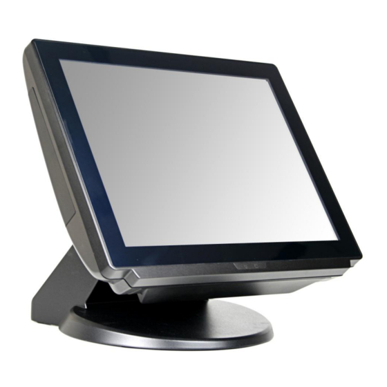
1.2. Quick Tour Front View and Side View LED Indicator The Power indicator will glow green when power is on. The HDD indicator will blink green when the HDD is accessed. Power switch Customer Display mounting hole cover MSR cover Wi-Fi antenna mounting hole HDD tray I/O cover... -
Page 8: Basic Peripherals Installation
DC in jack CD/DIO port RJ 50 port USB 3/4 port USB 1/2 port COM 2 port LAN 1 port VGA port LAN 2 port Parallel port COM 1 port 1.3. Basic Peripherals Installation 1. All cables and wires from peripherals to the POS device are recommended to be fed through the base in the direction as shown below. -
Page 9: Usb Mouse, Usb Keyboard, Usb Odd And Other Usb Devices
USB Mouse, USB Keyboard, USB ODD and other USB Devices Connect your USB Mouse, USB Keyboard and USB ODD to USB 1/2 or UBS 3/4 ports on the back panel of the device. LAN Cable Connect one end of RJ-45 LAN cable to the LAN 1 or LAN 2 port on the back panel of the device, another end to your internet device. -
Page 10: Customer Display
Customer Display A. Hardware Installation 1. Remove the two screws fixing the customer display cover, Remove the VFD mounting hole cover from the device and pull out the connector from the device. 2. Adjust angle for hinge of the VFD, and then connect to the device as shown below. - Page 11 B. Power Supply Configuration WARNING Never enable the 12V without the customer display attached and be sure to disable the 12V before removing the customer display. 1. Power up the XPOS855 and hit the DEL key to enter the BIOS. When the BIOS screen appears use the key on your external computer keyboard to select Advanced.
- Page 12 3. Highlight 12V, and then press the Enter key. 4. Press the ESC key to return to the BIOS SETUP UTILITY screen of step 1, use the key on your external computer keyboard to select the EXIT. Use the key to highlight Save Changes and Exit. Chapter 1...
-
Page 13: Msr
5. Press the Enter key, use the key to highlight the [Ok], press the Enter key again to save your voltage configuration and exit BIOS. 1. Remove the two screws fixing the MSR cover. 2. Remove the MSR cover from the device. Chapter 1... - Page 14 2. For MSR with fingerprint sensor or 2. For MSR or MSR with iButton, connect MSR with RFID sensor, connect the the connector of the MSR assembly to two connectors of the MSR assembly the device. to the device. MSR with iButton MSR with fingerprint sensor MSR with RFID sensor 3.
-
Page 15: Hdd Replacement
4. Finished. MSR with fingerprint sensor MSR with RFID sensor MSR withiButton 1.4. HDD Replacement 1. Loosen and remove the screws fixing the HDD tray. Chapter 1... - Page 16 2. Pull out the HDD tray slightly and softly. 3. Disconnect the SATA cable connector and SATA power cable connector. 4. Loosen and remove the four screws fixing the HDD, and then remove the HDD from the HDD tray. Chapter 1...
-
Page 17: Adjust Angle
5. Install the new HDD onto the device in reverse order. 1.5. Adjust Angle 1.6. VESA Wall-mount Kit Installation (X-PCC 854 only) 1. Install the device bracket. 2. Put the XPPC 855 onto the wall bracket which is preinstalled on the wall.. 1.7. -
Page 18: Basic Driver Installation
Basic Driver Installation 2.1. Before the installation 1. Connect an external USB CDROM to the USB port and insert the driver CD and turn on the device. The program auto runs and displays the DRIVER BANK screen. 2. Follow the on-screen instructions. 2.2. - Page 19 3. Click Next. 4. Read the License Agreement carefully and click Yes. 5. Click Next.
-
Page 20: Intel Management Engine Components Install
6. Click Next. 7. Click Finish. 2.3. Intel Management Engine Components install 1. On the main screen, click “XPS854/XPPC854 Series”. - Page 21 2. Click Intel Management Engine Driver 3. Click Next. 4. Click Yes.
- Page 22 5. Click Next. 6. Click Next. 7. Click Finish.
-
Page 23: Vga Driver Installation
2.4. VGA Driver Installation 1. On the main screen, click “XPOS854/XPPC854 Series. 2. Click VGA Driver. 3. Click VGA Driver For Windows XP /Windows 7/ Windows 8 32bit/64bit. - Page 24 4. Click Next. 5. Read the License Agreement carefully and click Yes. 6. Click Next.
-
Page 25: Lan Driver Installation
7. Click Next. 8. Select restart your computer right now or later, and then lick Finish. 2.5. LAN Driver Installation 1. On the main screen, click “XPOS854/XPPC854 Series”. - Page 26 2. Click Realtek Lan Windows XP/Windows 7/Windows 8 Driver 32bit/64bit. 2. The procedure starts. 3. Click Next 4. The driver starts install...
-
Page 27: Audio Driver Installation
4. Click Finish 2.6. Audio Driver Installation 1. The driver is preparing to install. - Page 28 2. Click Next. 3. Driver installation in progress...
-
Page 29: Touch Screen Driver And Software Utility Installation
4. Select restart your computer right now or later, and then lick Finish. 2.7. Touch Screen Driver and Software Utility installation 1. On the main screen, click “XPOS 854/XPPC854 Series”. 2. Click Touch Panel Driver. - Page 30 3. The procedure starts. 4. Click Next. 5. Check the Install PS/2 interface driver box and click Next.
- Page 31 6. Select an item according to your needs, and then click Next. 7. Click OK. 8. If you want to use Multi-Monitor, check the box and click Next. 9. Click Next.
- Page 32 10. Click Next. 11. The driver starts to install. 12. Click OK.
-
Page 33: Cash Drawer Driver Installation
2.8. Cash Drawer Driver Installation 1. On the main screen, please Click OPOS Cash drawer sample tool and source code. Click OPOS Cash drawer sample tool, OPOS Cash Drawer sample too source code, Cash drawer user manual, Cash drawer VB/DOS/tool/source code. - Page 34 Click Next button to install Cash drawer Drver. Click Next button...
- Page 35 Click Install button Click Finish button, if OPOS Common Obj is necessary, please check the “Insall OPOS CCOS v1.13 Run tome”...
- Page 36 Please wait the OPOS CCO v.1.13 utility initial. Click Next button Click Next button...
- Page 37 Click Next button Click Next button...
- Page 38 Click Next Click the Next button to begin the installation.
- Page 39 Please wait the install progress bar finish. Click the Finish button to exit the installer.
-
Page 40: Cash Drawer Function Introduction
2.9. Cash Drawer function introduction. Cash Drawer Configuration Before Open Cash Drawer Service, please configure the Cash Drawer configuration. FireTime: It can configuration the voltage pulse timing to open the Cash Drawer. Read Status Reverse: If the Cash Drawer is opened, but the Cash Drawer status is closed. Please click “Read Status Reverse”... -
Page 41: Open Cash Drawer
Open Cash Drawer Click the “Open Cash Drawer” button to open the Cash Drawer box. Cash Drawer Status will update, if the Cash Drawer box is opened. Cash Drawer Status “Check Cash Drawer“ button can re-check the Cash Drawer box status. Cash Drawer Status will show the Cash Drawer box status. -
Page 42: Wait For Drawer Close
Wait For Drawer Close If the Cash Drawer box is opened, click the “Wait For Drawer close” button will be about to begin a beeper/speaker sound. Beeper/Speaker Configuration Beeper configuration If the Cash Drawer box is not closed that out of the “Open Time Out”, the buzzer/speaker Open Time Out: Default is 5000 ms. -
Page 43: Close Cash Drawer Service
Close Cash Drawer Service Close Cash Drawer Service: It can close the Cash Drawer Service. It can click the “OK” button to exit the OPOS Cash Drawer Test App. -
Page 44: I/O Definition
I/O Definition Please refer the detailed technical information about all I/O ports as followings. 3.1. Power Connector Description Description GROUND +19V GROUND +19V 3.2. Serial Port COM Port 1/2/3 Description Description RI / 5V /12V 3.3. Cash Drawer Connector Description Description D_OUT0 D_OUT1... - Page 45 Cash Drawer Control Status Address Value Open 280H Bit 4 = 0 Close 280H Bit 4 = 1 Read Status 281H Bit 0 = 0/1...
-
Page 46: Specification
Specification... - Page 47 Main Board Intel® 3rd Gen. ULV Core Processor Core i7-3517UE 1.7 GHz / 2 core Core i3-3227U 1.9 GHz / 2 core Core i3-3217UE 1.6 GHz / 2 core Celeron 1037U 1.8 GHz / 2 core Celeron 1047UE 1.4 GHz / 2 core Chipset Intel®...
- Page 48 Power Input External adapter, 90W, 19VDC input Communication Wireless LAN module Color Black Material Aluminum EMC& Safety Compliance FCC / CE / VCCI Front Panel Protection IP66 compliance Back Cover Protection IP41 compliance Weight 6.43 Kg (appox.) Dimension 363W x 323D x 280H (mm) Operation Temperature 0°C ~ 35°C Storage Temperature...
Need help?
Do you have a question about the XPOS85-5W-D525 and is the answer not in the manual?
Questions and answers