Table of Contents
Advertisement
Quick Links
Advertisement
Table of Contents

Related Manuals for EBN Technology XPOS72-8B-A16G


Summary of Contents for EBN Technology XPOS72-8B-A16G
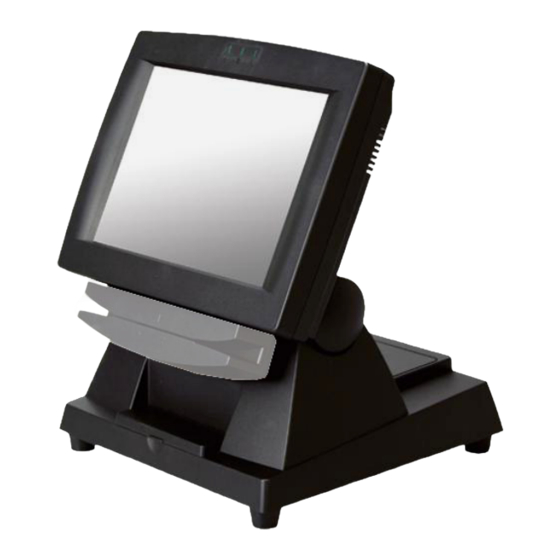
- Page 1 Service Manual XPOS72-8B-A16G...
-
Page 2: Liability Disclaimer
Copyrights ©2009. All rights reserved. The information in this document is subject to change without prior notice in order to improve reliability, design and function and does not represent a commitment on the part of the manufacturer. This document contains proprietary information protected by copyright. -
Page 3: Table Of Contents
Contents Copyrights ....................i Liability Disclaimer ...................i Contents....................ii 1. Before You Start ...................1 2. Opening the Device................2 3. Remove the CF card ................4 4. Touch Panel Control Board Disassembly ..........5 5. LED indicator Disassembly..............6 6. Power Switch Disassembly..............7 7. Mainboard and I/O Panel Disassembly ..........8 8. -
Page 4: Before You Start
Before You Start 1. Please unplug the power cable before you start to work. 2. Please read and follow the instructions in this document carefully. Failure to follow these instructions could damage your device and void the warranty. 1.1. Tools Suggested All procedures in this document require the following tools: #0 Phillips screwdriver #1 Phillips screwdriver... -
Page 5: Opening The Device
Opening the Device 1. Unplug all cables and plugs from the device. 2. Loosen and remove the four screws fixing the base unit by #1 Phillips screwdriver. 3. Remove the right hinge cover, left hinge cover and support cover as shown below. - Page 6 5. Un-tighten six screws on the back panel anticlockwise. 6. Separate the back panel from the front panel by lifting up and lay it down carefully. Chapter 2...
-
Page 7: Remove The Cf Card
Remove the CF card 1. Remove the CF Card slot cover. 2. Push the CF card eject button and remove the CF card. Chapter 3... -
Page 8: Touch Panel Control Board Disassembly
Touch Panel Control Board Disassembly 1. Remove: 1. Speaker connector, 2. LED indicator connector, 3. LCD connector, 4. inverter connector, 5. power switch connector, 6. touch panel connector from the mainboard. 2. Disconnect twoconnecters form the LCD inverter as shown below. 3. -
Page 9: Led Indicator Disassembly
LED indicator Disassembly 1. Pry the black plastic rectangle out and then the green LED out by slotted screwdriver. 2. Repeat the previous step to remove other LEDs. Chapter 5... -
Page 10: Power Switch Disassembly
Power Switch Disassembly 1. Remove the power switch from the device. Chapter 6... -
Page 11: Mainboard And I/O Panel Disassembly
Mainboard and I/O Panel Disassembly 1. Loosen the four hexagonal screws by 1.5 mm hexagonal socket spanner as shown below. 3. Loosen the four screws by #0 Phillips screwdriver as shown below. 4. Remove the mainboard from the device as shown below. Chapter 7... -
Page 12: Speaker Assembly Disassembly
Speaker Assembly Disassembly 1. Loosen the four screws by #1 Phillips screwdriver as shown below and remove the speaker assembly from the device. Chapter 8... -
Page 13: Lcd Panel Disassembly
LCD Panel Disassembly 1. Follow steps below: (1) Remove the black tape and disconnect the touch panel cable. (2) Remove the six screws by #1 Phillips screwdriver as indicated below. 2. Separate the LCD panel assembly from the front bezel by lifting up and lay it down carefully.
Need help?
Do you have a question about the XPOS72-8B-A16G and is the answer not in the manual?
Questions and answers