
Related Manuals for EBN Technology POS70-2EB-370


Summary of Contents for EBN Technology POS70-2EB-370
- Page 1 *POS70-2EB-370 *POS70-2EB-478 *POS70-5EB-370 *POS70-5EB-478 Mar. 2007 1/47 Version 1.2...
- Page 2 Copyright Notice The information in this document is subject to change without prior notice in order to improve reliability, design and function and does not represent a commitment on the part of the manufacturer. In no event will the manufacturer be liable for direct, indirect, special, incidental, or consequential damages arising out of the use or inability to use the product or documentation, even if advised of the possibility of such damages.
-
Page 3: Table Of Contents
Contents Chapter 1 – Introduction .................... 5 1.1 System Overview ..................5 1.1.1 System Outlook.................. 5 1.1.2 Rotating Angle ..................6 1.1.3 System Maintain................. 6 1.1.4 I/O Ports....................7 1.2 Specifications ....................8 Chapter 2 – Packing List..................12 Chapter 3 – Getting Started..................17 3.1 System setup .................... - Page 4 Introduction 4/47 Version 1.2...
-
Page 5: Chapter 1 - Introduction
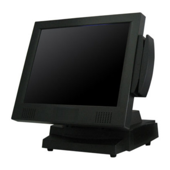
Chapter 1 – Introduction 1.1 System Overview 1.1.1 System Outlook Power LED HDD LED LAN LED TFT LCD Speakers HDD Case Customer Display (Options) MSR (Options) Maintaining screws Mounting hole for Pole Display or Display COM RI/5V/12V selection System Fan 5/47 Version 1.2... -
Page 6: Rotating Angle
1.1.2 Rotating Angle 1.1.3 System Maintain Remove 2 screws for system maintain 6/47 Version 1.2... -
Page 7: I/O Ports
1.1.4 I/O Ports Number Description AC Power Connector VGA (For 2nd display only) Printer Port (LPT) Cash Drawer 2 Cash Drawer 1 PS/2 Mouse PS/2 Keyboard Audio DC 24V (For Receipt Printer Power) Power USB (24V) Power USB (12V) USB x 2 COM 1 COM 2 COM 3... -
Page 8: Specifications
1.2 Specifications System Model SolidPOS 72 SolidPOS 75 POS70-2EB-370 POS70-5EB-370 POS70-5EB-478 POS70-5EB-478 Main Board P3: Intel Celeron / PIII 1.2GHz P4: Intel Mobile Celeron 1.2GHz , Celeron 2.0GHz , P4 2.0GHz P3: VIA CLE 266 (VT8623+VT8235) Core Logic P4: Intel 852GM + ICH4... - Page 9 Storage Temperature -20°C ~ 60°C Storage Humidity 20% - 85% RH, non-condensing Main Unit Ordering Information POS70-2EB-370 12.1” TFT SolidPOS W/ Intel P3 Socket 370 POS70-2EB-478 12.1” TFT SolidPOS W/ Intel P4 Socket 478, POS70-5EB-370 15” TFT SolidPOS W/ Intel P3 Socket 370, POS70-5EB-478 15”...
- Page 10 A10400121RH MSR+ I Button: 2 Tracks, KB Type and I Button PS/2 Type A10400120RH MSR+ I Button: 3 Tracks, KB Type and I Button PS/2 Type MSR+ Smart Card: 3 Tracks, RS-232 Type and Smart A10400104RH Card USB Type A10400005RH RFID : RS-232 Type WIRELESS LAN 802.11b/g MINI PCI MODULE W/ A10400266RH...
- Page 11 Packing List 11/47 Version 1.2...
-
Page 12: Chapter 2 - Packing List
Chapter 2 – Packing List The unit comes securely packaged in a shipping carton. Please contact your dealer if you find that anything is missing or damaged after examining the contents. The shipping carton should contain the following standard items : 2.1 Standard Items Main Unit Driver CD (Include manual) - Page 13 IDE extension cable HDD & CD-ROM power extension cable Power Cord (The picture varies from the area you locate) 13/47 Version 1.2...
-
Page 14: Optional Items
2.2 Optional Items Display Customer Display (LED, VFD, LCD) 3-in-1 Card Reader (MSR, Smart Card, i-Button) RFID 14/47 Version 1.2... - Page 15 15/47 Version 1.2...
- Page 16 Getting Started 16/47 Version 1.2...
-
Page 17: Chapter 3 - Getting Started
Chapter 3 – Getting Started 3.1 System setup Item Photo Description Plug-in power cord and connect with AC power Push “Start Button” 17/47 Version 1.2... -
Page 18: Hardware Installation
3.2 Hardware Installation 3.2.1 CPU Installation Item Photo Description Remove 2 screws Install CPU and apply the thermal adhesive Install thermal module 18/47 Version 1.2... -
Page 19: Memory Installation
3.2.2 Memory Installation The POS system supports memory up to 1 GHz with frequency of DDR266 and DDR333. Please follow the below procedures for installation. 1. Remove 2 screws from the system 2. Insert the memory module Item Photo Description Remove 2 screws Install Memory module 19/47... -
Page 20: Hdd Installation
3.2.3 HDD Installation Item Photo Description Remove 2 screws from HDD cover and pull out the metal case. Install HDD in the metal case. Slide the HDD into the POS system and connect IDE & Power Cable. Screw 2 screws on the HDD cover 20/47 Version 1.2... -
Page 21: Os Installation
3.2.4 OS Installation a. Please prepare a USB CD-ROM . b. Plug a USB CD-ROM into the USB port of POS system . c. Turn on the system and enter CMOS configuration page d. Set the boot up device as USB CD-ROM e. -
Page 22: Software Installation
3.3 Software Installation 3.3.1 Driver Installation Item Photo Description Insert driver CD and select POS 7series Select your model (P3 or P4) Install related driver 22/47 Version 1.2... - Page 23 23/47 Version 1.2...
-
Page 24: Touch Panel Calibration
3.3.2 Touch Panel Calibration Item Photo Description Execute “Touch Panel” from Windows Control Panel Click at “Calibration” Click at “Calibrate Now” 24/47 Version 1.2... - Page 25 Start calibrate 25/47 Version 1.2...
-
Page 26: Optional Items Installation
3.4 Optional Items Installation 3.4.1 MSR / RFID Install hardware Item Photo Description Remove 2 screws from POS system Remove plastic cover and inverter of system Install the MSR / RFID module on the system 26/47 Version 1.2... - Page 27 Connect MSR cable to CN12 Install inverter 27/47 Version 1.2...
- Page 28 Driver Installation Item No. Photo Description Insert driver CD and select POS 7series Select your model (P3 or P4) Install related driver 28/47 Version 1.2...
- Page 29 Also you could install it form the following path. (CD-ROM):\Driver\Options Driver\MSR(Megnetic Stripe Reader) Driver\Driver\Disk1\Setup.exe 29/47 Version 1.2...
-
Page 30: Pole Display
3.4.2 Pole Display Item Photo Description Remove plastic cover Install Pole Display Kit Connect RS232 cable to COM1 Note: Be sure to adjust jumper setting of COM1. Modify pin9 to supply 12V power. For more information, please refer to chapter 30/47 Version 1.2... -
Page 31: Nd Display
3.4.3 2 Display Hardware Installation Item Photo Description Remove plastic cover Adjust POS system angle Screw on 2 display and plug in the cable 31/47 Version 1.2... - Page 32 Display with touch panel If you order the 2 display comes with touch panel, please remember to adjust the COM port setting on the bottom side of POS system. So that it could supply 5V DC on pin 1 for touch panel. Note: 1.
- Page 33 BIOS setup 33/47 Version 1.2...
-
Page 34: Chapter 4 - Bios Setup
Chapter 4 – BIOS setup 4.1 P4 M/B (POS70-2EB-478, POS70-5EB-478) 4.1.1 Starting Setup To enter BIOS, please click at “Delete” when booting up the POS system and you will see the picture below. BIOS Information CPU Information Memory Information Function Key Time setup 34/47 Version 1.2... -
Page 35: Resolution Setup
4.1.2 Resolution setup Item Photo Description Enter “Northbridge Configuration” of “Chipset” Enter “Flat Panel Type” 12” Choose your panel type 12” – 800x600 15” – 1024x768 35/47 Version 1.2... - Page 36 15” 36/47 Version 1.2...
-
Page 37: P3 M/B
4.2 P3 M/B (POS70-2EB-370, POS70-5EB-370) 4.2.1 Starting Setup To enter BIOS, please click at “Delete” when booting up the POS system and you will see the picture below. BIOS Information BIOS Menu Function Key 37/47 Version 1.2... -
Page 38: Resolution Setup
4.2.2 Resolution setup Item Photo Description Enter “PCI / Plug and Play Setup” page of BIOS Select “LCD Panel Type” 12” Choose your panel type by “Page UP” & “Page Down” 12” – 800x600 15” – 1024x768 38/47 Version 1.2... - Page 39 15” 39/47 Version 1.2...
- Page 40 M/B Information 40/47 Version 1.2...
-
Page 41: Chapter 5 - M/B Information
Chapter 5 – M/B Information 5.1 P4 M/B Jumper Setting (POS70-2EB-478, POS70-5EB-478) Clear CMOS Setup If you want to clear the CMOS Setup (for example forgot the password you should clear the setup and then set the password again.), you should close the JP1 about 3 seconds, then open again. -
Page 42: P3 M/B Jumper Setting
Pentium 4 Mobile Celeron/P4-M LCD Power setting JP8: This jumper is for the setting of LCD panel voltage. Description +3.3V 5.2 P3 M/B Jumper Setting (POS70-2EB-370, POS70-5EB-370) Compact Flash Card Master/Slave Mode Setting JP1: Master/Slave Mode Setting Description OPEN SLAVE SHORT... - Page 43 JP2: This jumper is for the setting of LCD panel shift clock. Description Inverted Normal Clear CMOS Setup If you want to clear the CMOS Setup (for example forgot the password you should clear the setup and then set the password again.), you should close the JP5 about 3 seconds, then open again.
-
Page 44: Com & Rj-11 Jumper Settings
5.3 COM & RJ-11 Jumper Settings Before installing the cash drawer or any peripherals which use COM ports, please make sure you configure all the “Power” settings accurately. Cash Drawer Cash Drawer 5-6,7-8 1-2,3-4 2. COM1 & COM2 COM 1 Pin 1 Pin9 COM 2... - Page 45 Pin Assignment Assignment Assignment DOUT 0 DOUT 1 DIN 0 DIN 1 12V/24V 12V/24V I/O Address I/O Address: 280H (For both Cash Drawers which are controlled by data bit) Cash Drawer 1: DIN0=>Bit0, DOUT0=>Bit4 Cash Drawer 2: DIN1=>Bit1, DOUT1=>Bit5 45/47 Version 1.2...
- Page 46 Reversion 46/47 Version 1.2...
-
Page 47: Chapter 6 - Reversion History
Chapter 6 – Reversion History Version Item Descriptions Page 47/47 Version 1.2...
Need help?
Do you have a question about the POS70-2EB-370 and is the answer not in the manual?
Questions and answers