
Subscribe to Our Youtube Channel
Related Manuals for EBN Technology XPOS85-5W-D525


Summary of Contents for EBN Technology XPOS85-5W-D525
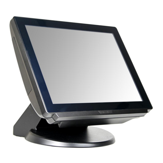
- Page 1 Service Manual XPOS85-5W-D525 XPOS84-5B-D525...
-
Page 2: Copyrights
Copyrights ©2012. All rights reserved. The information in this document is subject to change without prior notice in order to improve reliability, design and function and does not represent a commitment on the part of the manufacturer. This document contains proprietary information protected by copyright. -
Page 3: Table Of Contents
Contents Copyrights ....................i Liability Disclaimer ...................i Contents....................ii 1. Before You Start ...................1 1.1. Tools Suggested ..................1 2. Opening the Device and HDD Removal ..........2 2.1 HDD Removal ....................2 3. Mainboard side Components Replacement........4 4. Front-Panel side Component Replacement........8 Contents... -
Page 4: Before You Start
Before You Start 1. Please unplug the power cable before you start to work. 2. Please read and follow the instructions in this document carefully. Failure to follow these instructions could damage your device and void the warranty. 1.1. Tools Suggested All procedures in this document require the following tools: #0 Phillips screwdriver #1 Phillips screwdriver... -
Page 5: Opening The Device And Hdd Removal
Opening the Device and HDD Removal 2.1 HDD Removal 1. Remove the screw in the blue circle. 2. Pull the HDD tray out. 3. Disconnect the SATA/HDD power cable. Chapter 2... - Page 6 4. Remove the HDD as shown below. 5. Un-tighten four screws and remove the base from the POS device. 6. Un-tighten four screws. 7. Open the back panel. Chapter 2...
-
Page 7: Mainboard Side Components Replacement
Mainboard side Components Replacement 1. Open the two ejectors on the slot by pushing them, and remove the RAM from the slot. 2. Align and insert the new RAM into the slot and push both ends of the RAM down until the ejectors snap into place. 3. - Page 8 5. Disconnect: 1. speaker cable, 2. parallel port cable and 3. COM cable from the mainboard. 5.1 For XPOS85-5W-D525, disconnect the touch control bard cable from the USB connector. 6. Loosen the two screws by 1.5 mm hexagon socket spanner as shown below.
- Page 9 7. Loosen the four screws fixing the mainboard, and then remove the mainboard. 8. Loosen the six screws by 1.5 mm hexagon socket spanner as shown below, and then you can remove the COM3 port cable, VGA port cable and parallel port cable. Remove the power switch.
- Page 10 10. Remove the LED lens, and then separate the LED indicator from the LED lens. 11. Loosen the four screws to remove the speaker assembly. Chapter 3...
-
Page 11: Front-Panel Side Component Replacement
Front-Panel side Component Replacement Remove all black tapes. CAUTION: For XPOS85-5W-D525, there are a touch panel control board, insulation sheet and other cables equipped. Sub-steps under Step 1 below are for XPOS85-5W-D525. 1.1 Remove the insulation sheet. Chapter 4... - Page 12 1.2 Disconnect the two flexstrip cables linking the touch panel and the touch control board from the touch control board. 1.3 Disconnect the touch control cable from the touch control board. 1.4 Loosen the two screws and then remove the touch control board. Chapter 4...
- Page 13 2. Disconnect the touch cable. 3. Disconnect the LCD panel cable. 4. disconnect the three connectors. 5. Un-tighten the two screws and then you can remove the LCD inverter. Chapter 4...
- Page 14 6. Remove all four screws as shown and remove the LCD from the front touch assembly. 7. Remove the two screws per side, and then you can remove the LCD bracket. Chapter 4...
Need help?
Do you have a question about the XPOS85-5W-D525 and is the answer not in the manual?
Questions and answers