Table of Contents
Advertisement
Quick Links
Advertisement
Table of Contents

Related Manuals for EBN Technology X-POS855A


Summary of Contents for EBN Technology X-POS855A
- Page 1 User’s Manual X-POS855A...
-
Page 2: Liability Disclaimer
Copyrights communications. However, there is no guarantee that interference will not occur in a particular ©2013All rights reserved. The information in this installation. If this equipment does cause harmful document is subject to change without prior notice in interference to radio or television reception, which order to improve reliability, design and function and does can be determined by turning the equipment off and not represent a commitment on the part of the... -
Page 3: Weee Notice
WEEE Notice The WEEE mark applies only to countries within the European Union (EU) and Norway. This appliance is labeled in accordance with European Directive 2002/96/EC concerning waste electrical and electronic equipment (WEEE). The Directive determines the framework for the return and recycling of used appliances as applicable throughout the European Union. -
Page 4: Table Of Contents
Contents Copyrights ....................i Liability Disclaimer ................... i Regulatory Information ................i FCC Notices ......................i CE Notice ......................i WEEE Notice......................ii RoHS Notice ......................ii Safety Statement for Lithium Battery ..............ii Contents ....................iii ... -
Page 5: Hardware Setup
Hardware Setup 1.1. Packing Contents 1. Device X 1 5. IO Panel Cover X 1 2. Power Adapter X 1 6. Drive and Utility DVD X 1 3. Power Cord X 1 7. Wall mount kit (X-PPC855 only) 4. RJ50 to DB9 COM port adapter cable X 1 Chapter 1 Hardware Setup... -
Page 6: Quick Tour
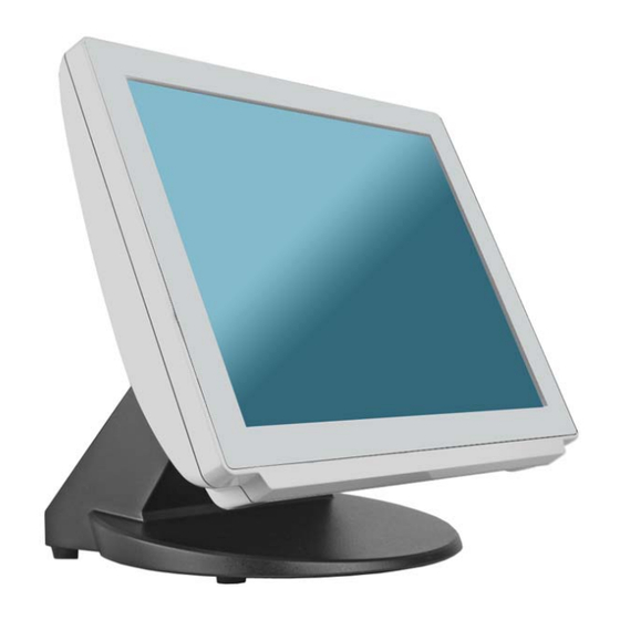
1.2. Quick Tour Front View and Side View LED Indicator The Power indicator will glow green when power is on. The HDD indicator will blink green when the HDD is accessed. Power switch Customer Display mounting hole cover MSR cover Wi-Fi antenna mounting hole HDD tray I/O cover... -
Page 7: Basic Peripherals Installation
Back Panel I/O DC-in jack Cash Drawer port RJ50 port for COM2 USB 3/4 port USB 1/2 port COM 3 port LAN 1 port VGA port LAN 2 port Parallel port COM 1 port CF card slot 1.3. Basic Peripherals Installation 1. - Page 8 Power Adapter 1. Assembly the power adapter to the power adapter bracket, and feed the DC connecter through the base. 2. Install the adapter bracket onto the POS device by tightening two screwsas shown. 3. Connect the DC connector of the power adapter to the DC-in jack. USB Mouse, USB Keyboard, USB ODD and other USB Devices Connect your USB Mouse, USB Keyboard and USB ODD to USB 1/2 or UBS 3/4 ports on the back panel of the device.
- Page 9 LAN Cable Connect one end of RJ-45 LAN cable to the LAN 1 or LAN 2 port on the back panel of the device, another end to your internet device. Cash Drawer Connect one end of RJ-11 cable to the Cash Drawer port on the back panel of the device, another end to your cash drawer.
- Page 10 Customer Display A. Hardware Installation 1. Remove the two screws fixing the customer display cover, Remove the VFD mounting hole cover from the device and pull out the connector from the device. 2. Adjust angle for hinge of the VFD, and then connect to the device as shown below.
- Page 11 B. Power Supply Configuration WARNING Never enable the 12V without the customer display attached and be sure to disable the 12V before removing the customer display. 1. Power up the X-POS855and hit the DEL key to enter the BIOS. When the BIOS screen appears use the or key on your external computer keyboard to select Advanced.
- Page 12 3. Highlight12V, and then press the Enter key. 4.Press the ESC key to return to the BIOS SETUP UTILITY screen of step 1, use the or key on your external computer keyboard to select the EXIT. Use the or key to highlight Save Changes and Exit. Chapter 1 Hardware Setup...
- Page 13 5. Press the Enter key, use the or key to highlight the [Ok], press the Enter key again to save your voltage configuration and exit BIOS. 1. Remove the two screws fixing the MSR cover. 2. Remove the MSR cover from the device. Chapter 1 Hardware Setup...
- Page 14 2. For MSR with fingerprint sensor or 2. For MSR or MSR with iButton, connect MSR with RFID sensor, connect the the connector of the MSR assembly to two connectors of the MSR assembly the device. to the device. MSR MSR with iButton MSR with fingerprint sensorMSR with RFID sensor 3.
-
Page 15: Hdd Replacement
4. Finished. MSR with fingerprint sensor MSR with RFID sensor MSR withiButton 1.4. HDD Replacement 1. Loosen and remove the screws fixing the HDD tray. Chapter 1 Hardware Setup... - Page 16 2. Pull out the HDD tray slightly and softly. 3. Disconnect the SATA cable connector and SATA power cable connector. 4. Loosen and remove the four screws fixing the HDD, and then remove the HDD from the HDD tray. 5. Install the new HDD onto the device in reverse order. Chapter 1 Hardware Setup...
-
Page 17: Adjust Angle
1.5. Adjust Angle 1.6. VESA Wall-mount Kit Installation (X-PCC855 only) 1. Install the device bracket. 2. Put the X-PPC855 onto the wall bracket which is preinstalled on the wall.. 1.7. Turn on the device 1. Make sure all peripherals are connected properly. 2. -
Page 18: Basic Driver Installation
Basic Driver Installation 2.1. Before the installation 1. Connect an external USB CDROM to the USB port and insert the driver CD and turn on the device. The program Auto Runs and displays the DRIVER BANK screen. 2. Follow the on-screen instructions. 2.2. - Page 19 4. Read the License Agreement carefully and click Yes. 5. Click Next. 6. Click Finish. Chapter 2 Basic Driver Installation...
-
Page 20: Vga Driver Installation
2.3. VGA Driver Installation 1. On the main screen, click “XPOS855/X-PPC855 Series”. 2. Click VGA Driver. 3. Click VGA Driver for WINDOWS. 4. Click Next. Chapter 2 Basic Driver Installation... - Page 21 5.Read the License Agreement carefully and click Yes. 6. Click Next. 7. Click Next. 8. Select restart your computer right now or later, and then lick Finish. Chapter 2 Basic Driver Installation...
-
Page 22: Lan Driver Installation
2.4. LAN Driver Installation 1. On the main screen, click “X-POS855/X-PPC855 Series”. 2. Click VIA 6130 LAN Drive. 3. The driver will be installed automatically. 4. Click OK on the pop-up message box. Chapter 2 Basic Driver Installation... -
Page 23: Audio Driver Installation
2.5. Audio Driver Installation 1. The driver is preparing to install. 2. Click Next. 3. Select “I Agree” and click Next. 4. Check “VIA HD Audio Codec Drive v7.300 30.090715” box, and then click Next. Chapter 2 Basic Driver Installation... - Page 24 5. Click Next. 6. Click Next. 7. Select restart your computer right now or later, and then lick Finish. Chapter 2 Basic Driver Installation...
-
Page 25: Touch Driver Installation (Only For Windows Xp)
2.6. Touch Driver Installation (Only for Windows XP) Single touch for Windows XP 1. On the main screen, click “X-POS855/X-PPC855 Series”. 2. Click Touch Panel Driver. 3. Click OK. 4. Software Installation - Click Continue Anyway. Chapter 2 Basic Driver Installation... - Page 26 Chapter 2 Basic Driver Installation...
- Page 27 5. Hardware Installation - Click Continue Anyway. 6. Click Exit. Chapter 2 Basic Driver Installation...
-
Page 28: I/O Definition
3.I/O Definition Please refer the detailed technical information about all I/O ports as followings. 3.1. Power Connector Description Description +19V GROUND +19V GROUND 3.2. Serial Port COM Port 1/2/3 Description Description RI / 5V /12V Chapter 3 IO Definition... -
Page 29: Cash Drawer
3.3. Cash Drawer Connector Description Description D_OUT D_IN Cash Drawer Control Status Address Value Open 280H Bit 4 = 0 Close 280H Bit 4 = 1 Read Status 281H Bit 0 = 0/1 Chapter 3 IO Definition... - Page 30 Dimens sion hapter 4 4 Dimen nsion...
-
Page 31: Specification
5Specification Main Board ® Intel Atom Processor D525 ® Chipset Intel ICH8-M System Memory 1 x 204 Pin DDR3 SO-DIMM Socket, up to 4GB Thermal Solution Fan-less ® Windows XP/ XPe/ WES, WEPOS, POSReady, ® Windows 7,Linux* Display TFT LCD Size 15”... -
Page 32: Dimension
EMC& Safety Compliance FCC / CE / VCCI Front Panel Protection IP66 compliance Back Cover Protection IP41 compliance Weight 6.43 Kg Dimension 363W x 296.2D x 219.6H (mm) Operation Temperature 0°C ~ 35°C Storage Temperature -20°C ~ 60°C Storage Humidity 20 –...
Need help?
Do you have a question about the X-POS855A and is the answer not in the manual?
Questions and answers