Table of Contents
Advertisement
Quick Links
Advertisement
Table of Contents

Related Manuals for EBN Technology XPOS75-5B-2930


Summary of Contents for EBN Technology XPOS75-5B-2930
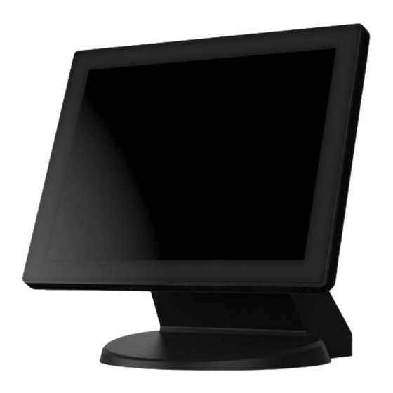
- Page 1 Service Manual XPOS75-5B-2930 XPOS75-5B-1900...
-
Page 3: Liability Disclaimer
Copyrights © 2014. All rights reserved. The information in this document is subject to change without prior notice in order to improve reliability, design and function and does not represent a commitment on the part of the manufacturer. This document contains proprietary information protected by copyright. -
Page 4: Table Of Contents
Contents Copyrights ....................i Liability Disclaimer ................. i Contents ....................ii 1. Before You Start ................. 1 2. Opening the Device ................2 3. RAM Disassembly ................3 4. HDD Disassembly ................4 5. Touch Panel Control Board Disassembly ........5 6.Power Switch Disassembly .............. -
Page 5: Before You Start
Before You Start 1. Please unplug the power cable before you start to work. 2. Please read and follow the instructions in this document carefully. Failure to follow these instructions could damage your device and void the warranty. 1.1. Tools Suggested All procedures in this document require the following tools: #0 Phillips screwdriver #1 Phillips screwdriver... -
Page 6: Opening The Device
Opening the Device 1. Loosen the screws on the VESA wall mount and remove the device from the base as shown. 2. Loosen two screws on the rear panel. 3. Separate the rear panel from the front panel by lifting up and lay it down carefully. -
Page 7: Ram Disassembly
RAM Disassembly 1. Release the two ejectors on the slot by pushing them, and remove the RAM from the slot. 2. Remove the old RAM. 3. Align and insert the new RAM in the slot and push both ends of the RAM down until the ejectors snap into place. -
Page 8: Hdd Disassembly
HDD Disassembly 1. Loosen the four screws by #1 Phillips screwdriver as shown below and remove the HDD assembly from the device. 2. Unplug one connector of the SATA cable and power cable from the HDD. 3. Loosen the four screws fixing the HDD and remove the HDD from the bracket as shown below. -
Page 9: Touch Panel Control Board Disassembly
Touch Panel Control Board Disassembly Remove: 1. LED indicator connector, 2. SATA cable, 3. LCD connector, 4 backlight connector, 5. power switch connector cable, 6 parallel port cable, 7. serial port cable, 8. Customer display cable, 9. USB cable and 10 speaker cable from the main board. -
Page 10: Power Switch Disassembly
6.Power Switch Disassembly 1. Remove the power switch from the device. Chapter 10... -
Page 11: Mainboard And I/O Panel Disassembly
7.Mainboard and I/O Panel Disassembly 1. Loosen the four hexagonal screws by 1.5 mm hexagonal socket spanner as shown below. 2. Loosen the four screws by #0 Phillips screwdriver as shown below. 3. Remove the main board from the device as shown below. Chapter 8... - Page 12 4. Remove the two screws by #1 Phillips screwdriver and remove the I/O panel. 5. Loosen the four hexagonal screws by 1.5 mm hexagonal socket spanner as shown below and you can remove the COM port and parallel port from the I/O panel.
-
Page 13: Speakers Disassembly
8.Speakers Disassembly 1. Loosen the four screws by #1 Phillips screwdriver as shown below and remove the speaker assembly from the device. Chapter 9... -
Page 14: Lcd Panel Disassembly
9.LCD Panel Disassembly 1. Loosen the fourteen screws in blue circle as shown below by #1 Phillips screwdriver. 2. Remove the LCD panel assembly and loosen the four screws holding the LCD. Chapter 10...
Need help?
Do you have a question about the XPOS75-5B-2930 and is the answer not in the manual?
Questions and answers