Table of Contents
Advertisement
Quick Links
Advertisement
Table of Contents

Related Manuals for EBN Technology PPC-815


Summary of Contents for EBN Technology PPC-815
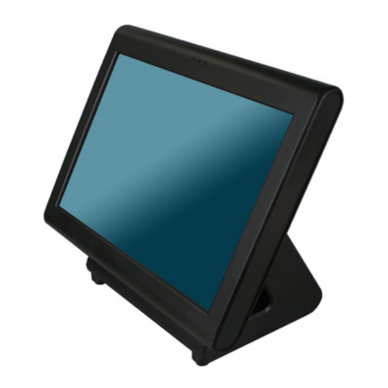
- Page 1 User’s Manual PPC-815 POS-815...
-
Page 2: Liability Disclaimer
Copyrights communications. However, there is no guarantee that interference will not occur in a particular ©2008 EBN Technology Corp. All rights reserved. The installation. If this equipment does cause harmful information in this document is subject to change without interference to radio or television reception, which... -
Page 3: Weee Notice
WEEE Notice The WEEE mark applies only to countries within the European Union (EU) and Norway. This appliance is labeled in accordance with European Directive 2002/96/EC concerning waste electrical and electronic equipment (WEEE). The Directive determines the framework for the return and recycling of used appliances as applicable throughout the European Union. -
Page 4: Table Of Contents
Contents Copyrights ....................i Liability Disclaimer ...................i Regulatory Information................i FCC Notices......................i CE Notice ......................i WEEE Notice......................ii Contents....................iii 1. Features ....................1 2. Unpacking the Box................2 3. Hardware Setup..................3 3.1. Quick Tour ....................3 Front View...................... 3 Back View ...................... 4 Back Panel I/O .................... - Page 5 6.1. Launch TouchKit Utility ................28 6.2. General......................29 6.3. Settings ....................... 30 6.4. Display ......................33 6.5. Edge Compensation .................. 36 6.6. How to Use Event Selector................ 38 7. I/O Definition..................39 7.1. Power Connector ..................39 7.2. Serial Port ....................39 7.3.
-
Page 6: Features
Features Intel® low power consumption and high performance technology Durable ultra-slim & robust die-casting aluminum chassis Smart Battery Backup (Optional) - supply voltage without any external power supply easy upgrade and assembly/disassembly 4x USB 2.0,1 x RS-485/422/232, 3x RS-232, Gigabit Ethernet port (RJ-11) and cash drawer port (RJ-11) equipped Wireless LAN supported Microsoft Windows series operation system (Windows XP Home Edition,... -
Page 7: Unpacking The Box
Unpacking the Box Verify that the box contains the following items. Greenland-70 All-in-One Touch POS System X 1 Power Adaptor X 1 Power Cord X 1 Driver and utility CD X 1 Chapter 2... -
Page 8: Hardware Setup
Hardware Setup 3.1. Quick Tour Front View LED Indicator The Power indicator will glow green when power is on. The HDD indicator will blink green when the HDD is accessed. The LAN indicator will blink green when transferring data though the LAN. Chapter 3... -
Page 9: Back View
Back View Back Panel I/O Note: For details of I/O ports on the back panel, please refer to Chapter 7 – I/O Definition. Chapter 3... -
Page 10: Connect Battery Pack (Optional)
3.2. Connect Battery Pack (Optional) Before power-on the device, please connect the battery to the mainboard: 1. Loosen the bolt. 2. Remove the device from the base unit. 3. Un-tighten two screws on the back panel anticlockwise. Chapter 3... - Page 11 4. Open the back panel. 5. Plug the power cable to the 9-pin power connector in the correct orient. Chapter 3...
- Page 12 6. Close the back panel and tighten two screws on the back panel. 7. Put the device onto the base unit. 8. Tighten the bolt. Chapter 3...
-
Page 13: Peripherals Installation
3.3. Peripherals Installation Power Adapter Connect the 4-pin output jack of the adapter to the DC 19V jack on the back panel of the device. USB Mouse, USB Keyboard and USB ODD Connect your USB Mouse, USB Keyboard and USB ODD to USB ports on the back panel of the device. -
Page 14: Cash Drawer
Cash Drawer Connect one end of RJ-11 cable to the Cash Drawer port on the back panel of the device, another end to your cash drawer. 1. Loosen the two screws and remove the plastic cover as shown. 2. Pull out the connector from the device and connect to the MSR. Chapter 3... -
Page 15: Vfd
3. Tighten the two screws to fix the MSR as shown. 4. Finished. 1. Assemble the parts of VFD as shown. Chapter 3... - Page 16 2. Install the part assembled in the Step1 to the device as shown. 3. Connect the VFD cable to the COM port as shown. 4. Pass the VFD cable through the base unit as shown. Chapter 3...
- Page 17 5. Assemble other parts of VFD as shown below. Note: 1. Be sure to adjust BIOS setting of COM port to supply 12V power. 2. For other info of VFD, Please refer to Customer Display manual. 6. Finished. Chapter 3...
-
Page 18: Turn On The Device
3.4 Turn on the Device 1. Make sure all peripherals are connected properly. 2. Press and hold the power switch until the power indicator on the front panel glow green. Chapter 3... -
Page 19: Driver And Utility Installation
Driver and Utility Installation 4.1. Before the installation All installation procedures described below are based on Microsoft Windows XP. 1. Connect an external USB CDROM drive to the USB port and insert the driver CD and turn on the device. The program autoruns and displays the DRIVER BANK screen. - Page 20 2. Click Next. 3.1. Click Next. 3.2. Read the License Agreement carefully and click Yes. 4. Click Next. Chapter 4...
-
Page 21: Vga Driver Installation
5.1. Select restart your computer right now or later. 5.2. Click Finish. 4.3. VGA Driver Installation 1. Click Graphic Driver. 2. Click VGA Driver for WIN2K/XP. Chapter 4... - Page 22 3. Click Next. 3.1. After files extracted, click Next on the welcome screen. 4. Read the License Agreement carefully and click Yes, and then the installation starts. 5.1. Select restart your computer right now or later. 5.2. Click Finish. Chapter 4...
-
Page 23: Lan Driver Installation
4.4. LAN Driver Installation 1. Click RTL81x0 LAN Driver. 1.1. On the welcome screen, click Next. 1.2. Click Install to begin the installation. 3. Click Finish. Chapter 4... -
Page 24: Audio Driver Installation
4.5. Audio Driver Installation 1. Click AC’97 Audio Driver. 2. Configures new software installation. 3. Click Configure Anyway. Chapter 4... -
Page 25: Wireless Lan Driver Installation
4. AC’97 drivers begins to install. 5.1. Select restart your computer right now or later. 5.2. Click Finish. 4.6. Wireless LAN Driver Installation 1. Click Wireless LAN Driver. Chapter 4... - Page 26 2. On the welcome screen, click Next, and then the installation begins. 3.1. Select restart your computer right now or later. 3.2. Click Finish. Chapter 4...
-
Page 27: Power Management
Power Management The backup battery equipped on Greenland 70 series is as “smart” as the battery for Notebook or handheld device; you can adjust any power management option that your unique hardware configuration supports. 5.1. Enter Power Option Properties Sheet There are two alternatives to enter Power Options Properties property sheet. -
Page 28: How To Set Power Options
2. Click Screen Saver tab, and then click Power button. Option 2: 1. Click Start, click Settings, click Control Panel, and then double-click Power Options. 5.2. How to Set Power Options Power Schemes Chapter 5... -
Page 29: Alarms
You can configure power settings under Power Schemes tab. Under Power schemes area, click the drop-down list to choose a power scheme to apply settings that fit the way you use Greenland 70. Under Settings for Home/Office Desk Power scheme area, set all parameters by clicking drop-down lists to put GREENLAND 70 on standby mode and turn off your monitor and hard disks automatically to save power upon your actual needs. - Page 30 Specify how much power level to activate these two alarms by dragging the green-white slider. Alarm Action Click Alarm Action to enter alarm actions setting sheet. On alarm actions setting sheet, select the type of alarm notification, which action GREENLAND 70 will take and which program will launch when the alarm occurs.
-
Page 31: Power Meter
Power Meter You can check power status under Power Meter tab. Check or uncheck the box to switch icon view and bar chart view. Under the icon mode, click the battery icon to show the detailed information about the battery. Chapter 5... -
Page 32: Advanced
Advanced You can specify power-saving settings by checking boxes in Options area and clicking drop-lists in Power button under Advanced tab. Hibernate Enable the hibernate function by checking Enable hibernation box. Chapter 5... -
Page 33: Touchkit Utility Quick Guide
TouchKit Utility Quick Guide 6.1. Launch TouchKit Utility There are two alternatives to launch TouchKit. Option 1: Under Microsoft Windows XP, click “start” menu and select “Programs”, under ”TouchKit” menu, click “Configure Utility”. Option 2: Click icon on the task bar to launch TouchKit utility. Chapter 6... -
Page 34: General
6.2. General The General tab in Touchkit utility shows all of TouchKit touchscreen controllers installed as below, including RS232, USB and PS2 interfaces. The function button is used for serial RS232 controllers only. Press this button to search the TouchKit serial controllers connected with the COM ports of Greenland 70. -
Page 35: Settings
is always shown in the controller list window. Remove This function button is used for serial RS232 controllers only. This button will be grayed and disabled automatically when the selected controller in the controller list window is not RS232 type. Press to remove and uninstall the selected serial RS232 controller from Greenland 70. - Page 36 Beep Beep On Touch Check this check box to enable driver to generate a beep sound when touch touchscreen state is switched from untouched to touched state. Beep On Release Check this check box to enable driver to generate a beep sound when touchecreen state is switched from touched state to untouched state.
- Page 37 value will affects the double click behavior for all of the mouse devices connected to Greenland 70. Two continuous clicks with this specified area in the specified double click time will be recognized as a double click event. Mouse Emulation Mode Change the emulation mode by pressing on this button.
-
Page 38: Display
Option You can set configuration for some advanced functions with this option button. Press this button, a pop up property sheet window will be popped up and shown as below. 6.4. Display TouchKit driver utility supports multiple monitor and display system. To work with multiple monitor system, you need to do proper configuration to map the touchscreen working area to the correct system display area. - Page 39 Please follow below instructions to do the configuration: Enable multiple monitor Check this check box to enable multiple monitor support and uncheck it to disable multiple monitor support. When this function is disabled, the touchscreen will be mapped to the primary monitor automatically. When this function is enabled, user can double click on the monitor area in the monitor geometry window to assign the monitor area where the touchscreen will be mapped.
- Page 40 Operation Mode TouchKit driver support split display mode for those applications which do not map the touchscreen to the full screen of the monitor. Full screen The touchscreen will be mapped to the full screen of the specified monitor. Right screen The touchscreen will be mapped to the right half screen of the specified monitor.
-
Page 41: Edge Compensation
The touchscreen will be mapped to the 4th quarter area of the specified monitor display. Customized If the touchscreen needs to be mapped the area other than the above area, user can define the mapping area for application. With this mode, the driver does not correct the mapping area when the display resolution changed. - Page 42 Bottom If you set the Edge to "Smaller", TouchKit will reduce the horizontal position of the bottom edge. If you set the Edge to "Larger", TouchKit will extend the horizontal position of the bottom edge. Left If you set the Edge to "Smaller", TouchKit will reduce the vertical position of the right edge.
-
Page 43: How To Use Event Selector
You can check Support Edge Compensation check box to enable/disable this function from left corner. Edge Compensation Button Click +10% or -10% button to adjust the smaller or larger of edge. If you click +10% button, the top, bottom, left and right edges will extend 10% of orientation to touch screen, and cursor will be moved 10 pixel of X and Y Axis to right and top. -
Page 44: I/O Definition
I/O Definition Please refer the detailed technical information about all I/O ports as followings. 7.1. Power Connector Description Description +19V GROUND +19V GROUND 7.2. Serial Port COM Port 1/2/3/4 Description Description RI / 5V /12V Chapter 7... -
Page 45: Ps2/Com
7.3. PS2/COM PS2/COM Description Description PIN Description PC_CLK )KEYBOARD) KB_DAT KB_CLK RI / 5V /12V PC_DAT KB_EN (KEYBOARD) 7.4. Cash Drawer Connector Description Description D_OUT D_IN Chapter 7... - Page 46 Cash Drawer Control Status Address Value Open 280H Bit 4 = 0 Close 280H Bit 4 = 1 Read Status 281H Bit 0 = 0/1 Chapter 7...
-
Page 47: Bios Setup
BIOS setup 1. Press and hold the power switch until the power indicator on the front panel glow green. 2. Before Windows launch, Press the “Delete” key to enter he BIOS. Chapter 8... -
Page 48: System Time And System Date Adjustment
8.1. System Time and System Date Adjustment 1. Under the Main tab, press the four arrow keys to high light the System Time and System Date to configure. 8.2. Serial ports Configuration 1. Press “ ” key to switch to “Advanced” tab and press “ ”... -
Page 49: Save Configuration Changes And Exit
8.4. Save Configuration Changes and Exit Press F10 key and highlight the [OK] on the message box and press the Enter Key. Chapter 8... -
Page 50: Specification
Specification Chapter 9... - Page 51 Main Board Intel Ultra Lo Voltage Celeron M 1GHz w/o L2 cache Intel Ultra Lo Voltage Celeron M 1.5GHz w 1MB L2 cache Chipset Intel 852GM + ICH4 System Memory SO-DIMM DDR 200/266, 128MB up to 1GB Fan-less Thermal Solution WinXP, WEPOS, WinCE.Net 5.0, Linux (Fedora Core 5, Suse 9) Storage Device 1 x IDE, 2.5”...
Need help?
Do you have a question about the PPC-815 and is the answer not in the manual?
Questions and answers