Table of Contents
Advertisement
Quick Links
Advertisement
Table of Contents

Related Manuals for Huvema HU 331 DGH


Summary of Contents for Huvema HU 331 DGH
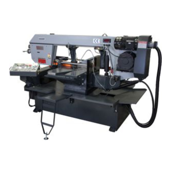
- Page 1 B A N D S A W M A C H I N E S HU 331 DGH...
-
Page 2: Table Of Contents
TABLE OF CONTENTS ACCIDENT PREVENTION AND SAFETY REGULATION ..............1 1.1 Advice for the operator......................... 1 1.2 The electrical equipment according to European Standard" CENELEC EN 60204-1"......1 1.3 Warning labels ............................. 1 1.4 Emergencies according to European Standard “CENELEC EN 60204-1” .......... 1 MACHINE TRANSPORTATION AND INSTALLATION............... - Page 3 331 dGh andsaw machine a. G eneral safety rUles for all machines N.B.: Read the instructions carefully in order to avoid any problems. As with all machinery there are certain hazards involved with operation and use of this machine. Using the machine with respect and caution will considerably lessen the possibility op personal injury.
- Page 4 B. a dditional safety rUles Always keep in mind that: • the machine must be switched off and disconnected from the power supply during maintenance and repairs, • clamped workpieces may only be measured when the machine is switched off. Never lean over the machine, mind loose clothing, ties, jewellery etc.
-
Page 5: Accident Prevention And Safety Regulation
ACCIDENT PREVENTION AND - The machine has been tested in conformity with point 20 of EN 60204 SAFETY REGULATION This machine has been designed to comply with Warning labels national and community accident- prevention regulations. Improper use and/or tampering with the safety devices will relieve the manufacturer of all responsibility. -
Page 6: Machine Transportation And Installation
MACHINE TRANSPORTATION AND - Environment temperature should fall within (-10ºC to + 50 ºC). INSTALLATION - Relative humidity cannot be over 90%. Machine dimensions Unpacking and Checking Contents The Metal Saw is shipped complete in one carton. Separate all parts from packing material and check each item with illustration and “Table of Loose Part”... -
Page 7: Attaching The Mobile Cover
- Securing the rear tray Attaching the trays requires 6 hex head bolt, 6 spring washers, 6 washers, and 6 nuts. Mobile cover Bolt point Remove mobile cover by lift handle up and pull it out from the base as showing direction when in this way miter cutting or position the vise to this side for another way miter cutting. -
Page 8: Securing To Foundation
Securing to foundation NOTE: The standards and legislation concerning Position the machine on a flat and level foundation refuse is in a constant state of evolution, therefore of reinforced concrete. Level machine and anchor is subject to changes. The user must keep it to the foundation with anchor bolts. -
Page 9: Indicator Lights
Indicator lights Chip tray 1. Coolant pump warning light 2 Hydraulic pump warning light 3. Vise pressure warning light 4. Open blade cover warning light 5. Broken blade warning light 6. Main motor warning light 7. Lower stroke limit indicator light 8. -
Page 10: Blade Speed Indicator
Blade speed indicator 3.12 Attached coolant device A digital display indicates the blade speed in MPM An attached coolant device that is screwed on the (FPM). This works in conjunction with speed front vise jaw for supply enough coolant to the changing dial to give you precise control of blade cutting material. -
Page 11: Set Up And Pre-Operations
SET UP AND PRE-OPERATIONS Placing the saw blade onto the drive wheel and flywheel - Disconnect from power supply Adjusting the tungsten carbide guides - Remove the blade guards The blade is guided by the upper ball bearings, - Turn the blade tension handle counter-clockwise, side ball bearings, and tungsten carbide guides. -
Page 12: Operation Preparations
OPERATION PREPARATIONS Setting the bow stroke limit Wing nut Waterproof cover Firstly uncover the retrieval cover by pull the cover up and out as arrow direction by the handle. Remove the auxiliary vise device by loosen the wing nut and move the device up and take it out from the table base. -
Page 13: Adjusting The Blade Speed
- Lock the cutting angle in place by using the lock - Raise the saw bow approximately 6” in height. lever. - Disconnect the machine from the power source. - Next, adjust the location of the vise or fence to - Remove both blade guides from the blade guide avoid contact with the blade. -
Page 14: Install The Vertical Press On The Vise Jaws For Bundle Cutting (Optional)
- Loosen C thumb knob for adjust the device rotate the bolt (D) to raise or lower the vise angle. press (E). - Adjust the vise press width to fit the work piece size. Loosen screws (F) on both sides of the vise press then move press extender bars (G) desired width. -
Page 15: Stopping Or Emergency Stopping
ROUTINE AND SPECIAL - Restart the hydraulic system. Press the hydraulic start switch 6.1 C. . MAINTENANCE - Start operation by using the start switch 6.1 I. The maintenance jobs are listed below, divided - The digital display 6.1 P will present pieces cut. into daily, weekly, monthly and six-month intervals. -
Page 16: Special Maintenance
Special maintenance TECHNICAL CHARACTERISTICS Special maintenance must be conducted by skilled personnel. We advise contacting your nearest Table of cutting capacity and technical dealer and/or importer. Other protective and details safety equipment, devices (of the reducer), the motor, the motor pump, and other electrical components also require special maintenance. -
Page 17: Noise Tests
NOISE TESTS The test was held under environmental noise levels of 65db. Noise measurements with the machine operating unload was 71db. Noise level during the cutting of mild carbon steel was 73db. NOTE: with the machine operating, the noise level will vary according to the different materials being processed. -
Page 18: Circuit Diagram
Control Circuit Diagram CHANGES AND T YPING ERRORS RESER VED CHANGES AND T YPING ERRORS RESER VED... - Page 19 Panel Board Wiring Diagram CHANGES AND T YPING ERRORS RESER VED...
- Page 20 Saw Bow Stroke Wiring Diagram CHANGES AND T YPING ERRORS RESER VED CHANGES AND T YPING ERRORS RESER VED...
-
Page 21: Part List & Explosion Drawings
PART LIST Part Part Description Size No. Q’ty Description Size No. Q’ty Base Fuse Seat 10x38-1P Hex. Cap Bolt M8x20 Ground Terminal Connector AVK10T Ground Terminal Connector Spring Washer HT-4E (Not shown, Non CE) Washer Terminal Connector AVK10 Terminal Connector Supporter HT-10 (Not shown, Not CE) - Page 22 PART LIST Part Part Description Size No. Q’ty Description Size No. Q’ty Handle Vise jaw-Right Angle Setting Hex. Socket Cap Screw M10x30 Hex. Socket Cap Screw M8x20 Hex. Socket Cap Screw M8x20 Set Block Vise Plate Button Head Socket Screw M6x8 Hex.
- Page 23 PART LIST Part Part Description Size No. Q’ty Description Size No. Q’ty Shaft Handle Mobile Fence Slide Bolt 229-1 Set Screw M8x8 Washer Blade Cover C Ring Button Head Socket Screw M5x8 Shaft Ø14x70 231-1 Button Head Socket Screw M6x12 Slide Free Set Shaft Device...
- Page 24 PART LIST Part Part Description Size No. Q’ty Description Size No. Q’ty Ø4x12 10x8x40 Cover Pulley Cover Round Head Screw M6x8 Button Head Socket Screw M5x8 Control Box Bracket Belt 1922V426 Button Head Socket Screw M6x8 Input Pulley Swiveling Bracket Hex.
- Page 25 CHANGES AND T YPING ERRORS RESER VED...
- Page 26 CHANGES AND T YPING ERRORS RESER VED CHANGES AND T YPING ERRORS RESER VED...
- Page 27 CHANGES AND T YPING ERRORS RESER VED...
- Page 28 CHANGES AND T YPING ERRORS RESER VED CHANGES AND T YPING ERRORS RESER VED...
- Page 29 CHANGES AND T YPING ERRORS RESER VED...
- Page 30 CHANGES AND T YPING ERRORS RESER VED CHANGES AND T YPING ERRORS RESER VED...
- Page 31 CHANGES AND T YPING ERRORS RESER VED...
- Page 32 CHANGES AND T YPING ERRORS RESER VED CHANGES AND T YPING ERRORS RESER VED...
- Page 33 CHANGES AND T YPING ERRORS RESER VED...
- Page 34 All rights reserved. No part of this booklet may be reproduced in any form, by print, photoprint, microfilm or any other means without written permission from the publisher. © Huberts bv, Kennedylaan 14, Veghel, the Netherlands. Internet: www.huvema.nl CHANGES AND T YPING ERRORS RESER VED CHANGES AND T YPING ERRORS RESER VED...
- Page 35 (in accordance with supplement II A of the Machinery Directive) Industrie & Handelsonderneming Huberts bv, Kennedylaan 14, 5466 AA Veghel, the Netherlands, in the capacity of importer, is to be held responsible for declaring that the Huvema machine: Bandsaw machine HU 331 DGH...
Need help?
Do you have a question about the HU 331 DGH and is the answer not in the manual?
Questions and answers