Advertisement
Quick Links
Advertisement

Related Manuals for Huvema HU 2613 VBS Super


Summary of Contents for Huvema HU 2613 VBS Super
- Page 1 OPERATION MANUAL HU 2613 VBS Super...
- Page 2 First of all, we would like to take this opportunity to thank you for selecting our Vertical Bandsaw. As you many understand, Vertical Bandsaw is a universal machine for contour cutting. If you choose a right blade, you are able to make any pattern cutting to any material with this machine. However, the most important thing is to realize how to operate it in a correct and skillful way, how to maintain it, and what about the construction of this machine.
- Page 3 ▲WARNING 1. Read the operator’s manual carefully. Learn the tools applications and limitations, as well as the specific potential hazards peculiar to it. Know your power tool. 2. Always wear approved safety glasses/face shields while using this machine. 3. Make certain the machine is properly grounded. 4.
-
Page 4: Initial Setting
HANDLING 1. Use a hook for the eyebolt that is equipped on the top of the machine. 2. To handle carefully with forklift chuck. CLEANING 1. Remove anti-rust oil. 2. Remove the coating with a clean brush applied with paraffin. 3. - Page 5 Capacity 658 * 335 mm Blade With Cap 3 ~ 25 mm Blade speed 15 ~ 1500 M/min Table size 600 * 700 mm ゚ ゚ Table tilt R-45 , L-10 Main Drive Motor 400 V, 3PHASE, 50HZ, 2.2 KW Grinder Motor 400V, 3PHASE, 50/60HZ, 0.04 KW Blade length...
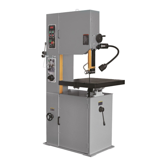
- Page 6 Control Board Upper Blade Guide Lock Knob Shear 10 Work Lamp Weld Board Blade Guide Supports Grinding Wheel Motor 12 Work Table Variable Speed Hand Wheel 13 Table Support Housing Hang Ring 14 Low/High Range Shift Lever Upper Wheel 15 Lower Wheel Post Elevating Hand Wheel - 5 -...
- Page 7 ▲CONTROL Low/High Range Shift Lever – Blade Tension Hand Wheel – Located on right side of machine base. Pull Located on underside of upper frame. Turn toward the front of the machine to shift into the clockwise to tension blade; counter-clockwise to low speed range.
-
Page 8: Blade Setting
BLADE SETTING 1. Assemble blade as illustrated. 2. Adjust blade tension according to the Tension Scale by turning the Blade Tension Adjust Hand Wheel. 3. Run machine to see if the blade tracks well or not, adjust blade tracking by turning Wheel Tilting Adjuster when it is necessary. - Page 9 GUIDE POST ADJUSTING 1. Loose the Guide Post Locker. ▲ WARNING 2. The height of the lower or upper Guide All adjustment or repairs to the machine must Post is according to the object. The be done with the power off and the machine disconnected from the power source.
-
Page 10: Blade Guide Adjusting
BLADE GUIDE ADJUSTING 1. Loose the inner hexagonal screws of the Blade Guide with an “L” shaped spanner. 2. Adjust the Blade Guide to be very close to the blade but do not be touched. 3. Lock the Blade Guides tightly. NOTE: There are totally four Blade Guides and two Guide Housings located above the table and under the table, all to be adjusted to the same position. -
Page 11: Tooth Shapes
To get the most satisfactory work, it is important to choose a blade that is correct for the work. Blade life, cut straightness, finishing quality and sawing efficiency is all related to the choice of blade. Blade breakage, teeth stripping, crooked cuts, and other common complaints are, in most instances, caused by using the wrong blades. - Page 12 SET SELECTION Always use rake set except: 1. For work of varying cross section use wave set. 2. When one blade must be used for a range of material sizes use wave set. Available set: Standard Carbon …………………………..………rake, wave Dart …………………………...….……...rake, wave Demon ………………………..……...……….
- Page 13 WIDTH SELECTION Always use widest blade: 1. Available in desired pitch (thin work only). 2. That will cut the smallest radius required. Gage is the thickness of the band. Set is the offset of the teeth 3. That the machine can handle. measured at their widest point.
- Page 14 Select saw blade in comply with the thickness of materials. Following suggestion might be helpful to you: A. Select a larger pitch blade for a thicker material. B. Select a smaller pitch blade for a thicker material. C. Use a smaller pitch blade to obtain a smooth cutting surface. D.
- Page 15 Thickness Sawing speed (M/min) for specified Material & thickness Pitch (No. of teeth / inch) Material ~1/4 1/4~1 ~1/4 1/4~1 1~3 High carbon steel Free cutting steel Ordinary tool steel High speed steel Stainless steel Thick iron plate Cast iron Aluminum 108,A108 A132, C133 13,43,85,4032,6151...
- Page 16 WELDER OPERATING GUIDE BLADE CUTTING 1. Cut the blade to the longest length for machine. Using the blade shear will insure that the blade ends are cut flat, square and smooth. 2. Lean the back of blade against the square cutting guide of the shear.
- Page 17 WELDER PREPARING BLADE CUITING If snips are used to cut blade, grind ends square as shown. Point to remember in preparing the blade for welding. ▲CAUTION: If the saw blade is rusty, the rust must be grounded off before the blade is welded. WELDING 1.
- Page 18 ANNEALING 1. Turn pressure knob to “0” position. 2. Release blade and position it at the front of the electrodes. (At the wider part) 3. Press annealing button. Do not release until the blade joint becomes as “orange” color. 4. Anneal #3 operations 4 or 5 times, gradually reducing the heat each time. 5.
- Page 19 GRINDING THE WELDED BLADE ▲ WARNING Keep hands away from rotating grinding wheel. Because it may be difficult to see if the wheel is rotating, a pilot light is provided. This light is “ON” when the grinder motor is running. After welding, the blade must be dressed to remove excess metal or flash from the weld.
-
Page 20: Secondary Annealing
SECONDARY ANNEALING Anneal the saw blade 2-3 times with lower temperatures. INSPECION OF THE WELD When the blade is removed from the welder it should be inspected carefully. The spacing of the teeth should be uniform and the weld should be located in the center of the gullet. - Page 21 MISALIGNED WELD (1) Dirt or scale on jaws or blade. (2) Blade ends on cut off square. (3) Blade ends not correctly aligned when clamped in jaws. (4) Worn jaws or inserts. (5) Jaws are not aligned correctly. MISALIGNED WELD-BLADE ENDS ARE OVERLAPPED (1) Jaw Upset Force Control set for wider blade than used, adjust correctly.
-
Page 22: Troubleshooting
TROUBLE SHOOTING TROUBLE REASON SHOOTING The Weld could not be made, the A. The wire connection is poor, the A. Change a switch or grind the Jaws do not move connecting point of welding switch connecting point with a life is bad B. - Page 23 TROUBLE REASON SHOOTING Saw blade is twisted A. Improper welded A. Re-weld the blade again B. Blade installed in improper way B. Set the guide inserts closer C. The blade is overdone C. Increase blade tension D. Decrease feeding rate when start cutting E.
- Page 24 PART OR PLACE TO BE KIND OF OIL LUBRICATING REMARKS OILDED OR GREASED OR GREASE PERIOD Gear Box: not for VBS-1408 Bearings Mechanism oil every 6 months (clean up every day) Guide post sliding part Grease every 7 days #1350 & #1360 #0600,# 0740, #7120 &...
- Page 26 GEAR BOX COMPONENT GUIDE POST COMPONENT 0500 GEAR BOX 1311 GUIDE SUPPORT, UPPER 0510 GEAR BOX COVER 1312 GUIDE SUPPORT, LOWER 0520 GEAR 1320 BLADE GUIDE 0521 GAER 1331 BLADE STOPPER, LONG 0530 SCREW NUT 1332 BLADE STOPPER, SHORT 0531 SCREW NUT 1333 ECCENTYIC SHAFT...
- Page 27 AIR PUMP COMPONENT VARIATOR COMPONENT 4060 AIR PUMP SEAT 7000 MOTOR SPRING HOUSING 4170 AIR NOZZLE 7010 SPRING 4180 AIR NOZZLE CLIPPER 7020 VAEIATOR DISK, UPPER OUTER 4450 AIR COMPRESSOR 7030 VAEIATOR DISK, UPPER INNER BA60 V-BELT, 2011+4450 7040 VARIATOR HOUSING TUBE 7050 VARIATOR SHAFT 7060...
- Page 29 WELDER COMPONENT WORK LAMP COMPONENT 6010 LIMIT SWITCH 6801 WORK LAMP COMPONENT 6011 INSULATOR 6020 GUIDE BLOCK 6021 SPRING BRACKET 6030 GUIDE CASTING 1900 SHEAR COMPONENT 6040 HOUSING 6050 STATIONARY JAW 1910 SPINDLE BUSHING 6051 INSULATOR 1920 SPINDLE LIFT 6052 INSULATING TUBE 1930 BLADE SHAFT...
- Page 30 - 29 -...
- Page 32 SCHEDULE OF ELECTRICAL EQUIPMENT Item Designation Technical date Supplier Suppliers Inspection reference Standard EN60947-5-1 WELD ON 2<<a>> WHITE Y.K. YS-FUC-22-12-1 EN60947-5-1 ANNEAL ON 2<<a>> GREEN Y.K. YS-FUC-22-12-3 EN60947-5-1 EMERGENCY STOP 2<<a<b>> RED Y.K. YS-L1-5 EN60947-5-1 MAIN MOTOR OFF 1<<a<b>> RED Y.K.
- Page 33 SCHEDULE OF ELECTRICAL EQUIPMENT Item Designation Technical data Supplier Suppliers Inspection reference Standard TB1 TERMINAL BOARD 600V, 25A TEND TB25-12 TB2 TERMINAL BOARD 600V, 25A TEND TB25-12 EN60269-1 FU1 FUSE 10 X 38 120KA/500V~ SOCOMEC 10AgG EN60269-1 FU2 FUSE 10 X 38 120KA/500V~ SOCOMEC 10AgG...
Need help?
Do you have a question about the HU 2613 VBS Super and is the answer not in the manual?
Questions and answers