
Subscribe to Our Youtube Channel
Related Manuals for Pentair RAYCHEM RAYSTAT-CONTROL-10


Summary of Contents for Pentair RAYCHEM RAYSTAT-CONTROL-10
- Page 1 RAYSTAT-CONTROL-10 Control thermostat thermostat thermostat de Contrôle Thermal Building SoluTionS Raychem-IM-INST195-RaystatControl10-ML-1701...
-
Page 2: Table Of Contents
engliSh Table of contents ��������������������������������������������������������������������������������������� 2 Description & Technical data ��������������������������������������������������������������������� 6 Functional description ������������������������������������������������������������������������������� 7 Display �������������������������������������������������������������������������������������������������������� 7 Installation description ������������������������������������������������������������������������������ 8 Operational description ��������������������������������������������������������������������������� 11 Testing, commissioning and maintenance ���������������������������������������������� 15 Wiring diagrams ��������������������������������������������������������������������������������������� 37 Commissioning sheet ������������������������������������������������������������������������������ 39 deuTSch inhaltsverzeichnis �������������������������������������������������������������������������������������... - Page 4 1� 3� 2� 5� 4� 6�...
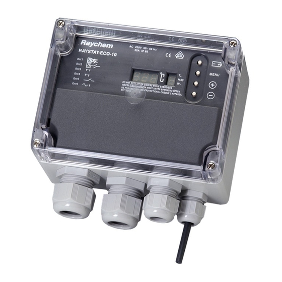
- Page 5 engliSh a 1. Thermostat enclosure B 1. Terminal screwdriver 3 mm 2, 3, 4, 5. Cable entries 2. Posi-drive screwdriver 5 mm (2 x M25, 1 x M20, 1 x M16) 3. Trimming knife 6. Temperature sensor Pt 100 4, 5, 6. Spanners 7.
-
Page 6: Description & Technical Data
RAYSTAT-CONTROL-10 is necessary� Installation and all wiring must be in accordance with applicable regulations� The device must be installed in non hazardous areas only� Pentair Thermal Management offers other controls for use in hazardous areas� Technical data Supply voltage: 230 Vac�... -
Page 7: Functional Description
Mounting: on a wall or directly on the pipe using support brackets, SB-100 / SB-101 / SB-110 T sensor Type: 3-wire Pt 100 according to IEC Class B Sensor head: 50 mm x ∅ 5 mm Cable length: 3 m* Cable diameter: 4 mm Cable exposure T:... -
Page 8: Installation Description
For selection of industrial heating cables, follow the Selection Guide for Industrial Trace-Heating Systems or use the latest version of TraceCalc or contact your Pentair Thermal Management representative� Follow the design guidelines and install the system in accordance with the system specifications�... - Page 9 Mount the enclosure using wall fasteners (screws) via the four, 4 mm ∅ holes� B. mounting on a pipe Pentair Thermal Management offers different support brackets (not included) to mount the RAYSTAT-CONTROL-10 on a pipe: SB-100, SB-101 or SB-110� 3. Wiring Remove the terminal protection cover to access the terminals�...
- Page 10 4. installation of the sensor 20 mm 90° location – as indicated in the system design documentation – not on valves, flanges, supports, pumps or other heat sinks – at the top of the pipe for thermally sensitive pipe contents (A) –...
-
Page 11: Operational Description
Remark: The sensor cable can be extended up to 150 m when a cross section of 3 x 1,5 mm² is used (max� 20 Ω per conductor)� The connection between sensor cable and sensor extension can be made in junction box JB-86 or equivalent�... - Page 12 operaTional deScripTion 1. introduction The RAYSTAT-CONTROL-10 parameters are configured via a menu system� The unit is delivered with a battery so that the operating parameters can be set up without any need for the power supply to be connected� This is useful for setting units on the bench prior to mounting in their working location or on site when power isn’t available�...
- Page 13 To alter any parameter shown in the display, press the + or – keys� This will allow the parameter to be raised or lowered to the maximum or the minimum in integer steps� If you require to reset all parameters to their default value, press the + and –...
-
Page 15: Testing, Commissioning And Maintenance
TeSTing, commiSSioning and mainTenance Test heating cable when thermostat installation is complete as directed in the Pentair Thermal Management instructions applicable for the heating cable� Fill out the commisioning sheet (page 39)� Maintain thermostat during normal plant maintenance� Check: Mounting is firm... -
Page 16: Beschreibung & Technische Daten
Ansteuerung eines Leistungsschützes� Die Installation und der Anschluss der Steuerung müssen entsprechend den örtlich geltenden Bestimmungen erfolgen� Der Thermostat RAYSTAT-CONTROL-10 darf nicht in explosionsgefährdeten Bereichen installiert werden� Für explosionsgefährdete Bereiche bietet Pentair Thermal Management spezielle Thermostate an� Technische daten Betriebsspannung: AC 230 V, +10%/–10%, 50/60 Hz... -
Page 17: Funktionsbeschreibung
gehäuse Umgebungstemperatur- bereich: –40°C bis +80°C Schutzart: IP65 Bohrungen: 2 x M25, 1 x M20, 1 x M16 Abmessungen: 120 x 160 x 90 (mm) Gewicht: ca� 800 g Material: Graues Polycarbonat Deckelbefestigung: 4 x M6, Zylinderkpfschrauben - rostfreier Stahl, unverlierbar Montage: Wandmontage oder auf Befestigungswinkel SB-100, SB-101, SB-110... -
Page 18: Display
Bautechnik finden Sie in unserem Technischen Handbuch� Eine detaillierte Auswahlhilfe für industrielle Beheizungssysteme von Pentair Thermal Management finden Sie in unserer Projektierungsanleitung, bzw� in unserer speziell entwickelten Planungssoftware „TraceCalc“� Für Fragen zu individuellen Anwendungen wenden Sie sich bitte direkt an Ihre Pentair Thermal Management- Vertretung�... - Page 19 Wandmontage Für die Wandmontage sind vier Löcher für M4-Schrauben im Gehäuse� B. montage auf der rohrleitung Pentair Thermal Management bietet auch Befestigungswinkel (nicht im Lieferumfang enthalten) für die Montage auf der Rohrleitung an: SB-100 / SB-101 / SB-110� 3. anschluss Entfernen Sie zuerst die Gehäuseabdeckung�...
- Page 20 Hinweis: Für potentialfreien Betrieb müssen die Verbindungskabel (W1 und W2) entfernt werden, da sonst der Thermostat oder andere, daran angeschlossene Komponenten beschädigt werden können� Bei kritischen Prozessen oder extrem niedrigen Umgebungstemperaturen (unter -25°C) wird die Verwendung einer externen Alarmeinheit empfohlen� Diese kann über die M20-Verschraubung 4 direkt am Thermostaten angeschlossen werden�...
- Page 21 Warnung: Montieren Sie den Sensor nicht bei Umgebungstemperaturen unter –20°C� Verbiegen Sie den Sensor auf keinen Fall (die letzten 50 mm)� Der minimale Biegeradius für das Sensorkabel beträgt 10 mm� anschluss des Sensors am Thermostaten Führen Sie das Sensorkabel durch die dafür vorgesehene M16- Verschraubung 5 und schließen Sie es entsprechend dem Anschlussdiagramm auf Seite 37 an�...
-
Page 22: Programmierung
FunkTionSBeSchreiBung 1. einleitung Die RAYSTAT-CONTROL-10 Parameter sind über ein System-Menü einstellbar� Der Thermostat ist zusätzlich mit einer Batterie (im Lieferumfang) ausgestattet, so dass die Programmierung auch ohne Netzspannungsanschluss vorgenommen werden kan� Bitte beachten Sie, dass die Batterie-Taste ( ) nur gedrückt werden darf, wenn der Thermostat nicht unter Netzspannung steht, da sich die Batterie ansonsten sofort entlädt�... - Page 23 3. parameter Der erste angezeigte Parameter im Display während des Programmiermodus ist die Haltetemperatur (Sollwert)� Andere Parameter, Werkseinstellungen, Minimum- und Maximumwerte können aus der folgenden Tabelle entnommen werden� parameter Werkseitige code min. max. einstellung Haltetemperatur (°C) Hysterese (K) Untertemperaturalarm (°C) –40 Übertemperaturalarm (°C) Begleitheizung bei...
-
Page 25: Test, Inbetriebnahme Und Wartung
TeST, inBeTrieBnahme und WarTung Nachdem Sie den Thermostat montiert haben, prüfen Sie, ob die Heizleitung ordnungsgemäß funktioniert� Hinweise zur Überprüfung finden Sie in der Montageanleitung der Heizleitung� Nun füllen Sie das Inbetriebnahmeprotokoll aus (Seite 39)� Der Thermostat sollte in regelmäßigen Abständen gewartet werden� Prüfen Sie, ob –... -
Page 26: Description & Caractéristiques Techniques
(25 A)� Il est conçu pour réguler les systèmes de traçage électrique Pentair Thermal Management� Le ruban chauffant est commandé (MARCHE/ ARRÊT) soit directement par le RAYSTAT-CONTROL-10 soit par le biais d’un contacteur�... -
Page 27: Fonctionnement
Boîtier Température de service : –40°C à +80°C Protection : IP 65 Entrées : 2 x M25, 1 x M20, 1 x M16 Dimensions : 120 x 160 x 90 mm Poids approx� : 800 g Matériau : polycarbonate Fixation couvercle : 4 vis captives Montage : sur paroi ou support de fixation sur la... -
Page 28: Afficheur
aFFicheur Le RAYSTAT-CONTROL-10 est équipé d’un afficheur numérique� Les trois chiffres de gauche 9a correspondent à la valeur mesurée et le chiffre de droite 9b est un affichage d’état� Quatre modes d’affichage sont possibles: 1� En fonctionnement normal (absence d’erreur), la température mesurée ou la température de consigne s’affichent dans la partie gauche de l’afficheur (alternativement)�... -
Page 29: Installation
Pour les rubans chauffants destinés à l’industrie, voir le Guide de sélection industrie, utiliser la dernière version du logiciel TraceCalc ou encore prendre contact avec votre agent Pentair Thermal Management� Respecter la marche à suivre et procéder à l’installation en conformité... - Page 30 3. câblage Ôter le capot du bloc de connexion pour accéder aux bornes de raccordement� alimentation: Faire passer un câble monophasé (230 Vca) dans le presse-étoupe 2 , taille M25 (schéma A ) et raccorder selon le schéma électrique de la page 37�...
- Page 31 4. installation de la sonde 20 mm 90° emplacement – conforme aux spécifications de l’étude – éviter les vannes, robinets, supports, pompes ou autres points chauds – sur le dessus de la tuyauterie pour les fluides sensibles à la chaleur (A) – à la limite du quart inférieur de la circonférence en cas de ruban chauffant unique (B) –...
- Page 32 raccordement de la sonde au raySTaT-conTrol-10 Faire passer le câble de la sonde dans le presse-étoupe 5 (M16) et raccorder selon le schéma électrique de la page 37� Les codes couleur du câblage doivent être respectés� Remarque: Le câble de la sonde peut être prolongé jusqu’à 150 m avec un câble de section 3 x 1,5 mm²...
-
Page 33: Paramétrage
paraméTrage 1. introduction Les paramètres du RAYSTAT-CONTROL-10 se programment grâce à un système de menu� L’appareil est fourni avec une pile, ce qui permet de régler les paramètres d’exploitation sans branchement à l’alimentation réseau� Les thermostats peuvent ainsi être réglés en atelier avant leur installation sur le lieu d’utilisation mais aussi sur site quand l’alimentation électrique n’est pas disponible�... - Page 34 Si vous désirez réinitialiser tous les paramètres à leur valeur par défaut, appuyer simultanément sur les deux touches Plus + et Moins – pendant environ 2 secondes� Si cela est positif, l’afficheur indique � 3. paramètres Le premier paramètre indiqué pendant le mode paramétrage est le point de consigne�...
-
Page 36: Test, Mise En Service Et Entretien
TeST, miSe en SerVice eT enTreTien Procéder à l’essai du ruban chauffant à la fin de l’installation du thermostat conformément aux instructions concernant le ruban chauffant� Compléter la fiche de mise en service (page 39)� Vérifier et entretenir le thermostat lors des maintenances régulières des installations�... -
Page 37: Wiring Diagrams
a. Wiring diagrams anschlussdiagramm Schémas électriques Max. C 25 A 30 mA RAYSTAT-CONTROL-10 5 L L 8 N N A B C alarm* 2A max. R: Same colour R: die gleiche Farbe R: la même couleur Heating cable Temp� Pt 100 sensor * Optional Heizband Temp�... - Page 38 B. Voltage free operation: remove links W1 and W2 and change “u” parameter in set up mode from “0” (not volt free) to “1” (volt free) as explained on page 13 of this manual. potentialfreier Berieb: entfermen Sie die Brücken W1 und W2 und ändern Sie die den parameter für potentialfreien Betrieb “u”...
- Page 40 Fax +385 1 605 01 88 salesee@pentair�com saleskz@pentair�com www.pentairthermal.com Pentair is owned by Pentair or its global affiliates� All other trademarks are the property of their respective owners� Pentair reserves the right to change specifications without prior notice� © 2013-2017 Pentair� Thermal Building SoluTionS...
Need help?
Do you have a question about the RAYCHEM RAYSTAT-CONTROL-10 and is the answer not in the manual?
Questions and answers