Advertisement
Quick Links
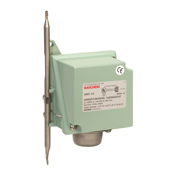
AMC-1A
Ambient-sensing thermostAt for nonhAzArdous locAtions instAllAtion instructions
4.9 in (124 mm)
4.5 in (114 mm)
4.0 in (102 mm)
8.0 in
(202 mm)
Removable
knob cover
3.0 in (76 mm)
Terminal
block
3⁄4 in
NPT conduit entry
WARNING:
This component is an electrical device. It must be installed
correctly to ensure proper operation and to prevent shock or
fire. Read these important warnings and carefully follow all the
installation instructions.
IndustrIal Heat tracIng solutIons
R
4.0 in
(102 mm)
4.5 in
(114 mm)
5.6 in
(142 mm)
Adjusting
Ø.28 in (7 mm)
knob
mounting holes (2X)
0.3 in
(9 mm)
1.2 in
(30 mm)
0.8 in
(20 mm)
Component approvals and performance are based on the use of
specified parts only. Do not use substitute parts or vinyl electrical
tape to make connections.
EN-RaychemAMC1A-IM-H56908 9/15
Description
The AMC-1A thermostat is designed for controlling freeze
protection heat-tracing systems in nonhazadous locations. The
thermostat responds to ambient temperature changes. The
AMC-1A can be used to control a heat-tracing circuit directly (see
Figure 1 on back page) or it can be used to control a contactor coil
(see Figure 2).
ApprovAls
specificAtions
Enclosure
NEMA 4X, polyurethane-coated cast-
aluminum housing, stainless-steel hardware
Entries
One 3/4 in. NPT conduit hub
Set point range
15°F to 140°F (–9°C to 60°C)
Sensor exposure
–40°F to 160°F (–40°C to 71°C)
limits
Housing exposure
–40°F to 160°F (–40°C to 71°C)
limits
Switch
SPDT
Electrical rating
22 A at 125/250/480 Vac
Accuracy
±6°F (±3.3°C)
Deadband
2°F to 12°F (1.1°C to 6.7°C) above actuation
temperature
Set point
±3°F (±1.7°C)
repeatability
Sensor type
Fixed fluid-filled (silicone) bulb and capillary
Sensor material
300 series stainless steel
Connection
Screw terminals, 10–14 AWG (2–5 mm
terminals
2
)
1 / 2
Advertisement

Related Manuals for Pentair RAYCHEM AMC-1A


Summary of Contents for Pentair RAYCHEM AMC-1A
-
Page 1: Specifications
AMC-1A Ambient-sensing thermostAt for nonhAzArdous locAtions instAllAtion instructions Description The AMC-1A thermostat is designed for controlling freeze protection heat-tracing systems in nonhazadous locations. The thermostat responds to ambient temperature changes. The AMC-1A can be used to control a heat-tracing circuit directly (see Figure 1 on back page) or it can be used to control a contactor coil (see Figure 2). -
Page 2: Installing The Thermostat
Fax: +1.650.474.7711 thermal.info@pentair.com Pentair and AMC are owned by Pentair or its global affiliates. All other trademarks are the property of their respective owners. Pentair reserves the right to change specifications without prior notice. © 2001-2015 Pentair. PN 689375 IndustrIal Heat tracIng solutIons EN-RaychemAMC1A-IM-H56908 9/15...
Need help?
Do you have a question about the RAYCHEM AMC-1A and is the answer not in the manual?
Questions and answers