
Related Manuals for Pentair NRG-Temp


Summary of Contents for Pentair NRG-Temp
- Page 1 NRG-Temp Software version 3.2 210116 CZ – DA- DE- EN – ES – ET – FI – FR – HU – IT – LT – LV – NL – NO – PL – RU – SV pentairthermal.com/manuals/ THERMAL BUILDING SOLUTIONS...
- Page 2 70.5 70.5 Figure 1 Figure 2...
-
Page 3: Table Of Contents
3.1 Mounting the Thermostat 3.2 Mounting the Floor Sensor 3.3 Connection of the Thermostat to the power supply 3.4 Product specific information 3.4.1 NRG-Temp in combination with T2QuickNet heating mat 3.4.2 NRG-Temp with the T2Red (T2Reflecta) self-regulating cable EcoHome Getting started Navigation •... - Page 4 User settings ( 7.1 The standard User Menus 7.1.1 User Menu 1: Sensor Setting 7.1.2 User Menu 2: Service read out 7.1.3 User Menu 3: Calibration of the floor temperature (offset value) 7.1.4 User Menu 4: Calibration of the room temperature (set value) 7.1.5 User Menu 5: Display back-light “on”...
- Page 5 Other features 8.1 Learning feature 8.2 Key lock feature 8.2.1 Lock: 8.2.2 Unlock: 8.3 External Set Back feature (Pilot Wire) Trouble shooting Reset to factory settings Technical specification Approvals and declarations ATTENTION This appliance can be used by children aged from 8 years and above and persons with reduced physical, sensory or mental capabilities or lack of experience and knowledge if they have been given supervision or...
-
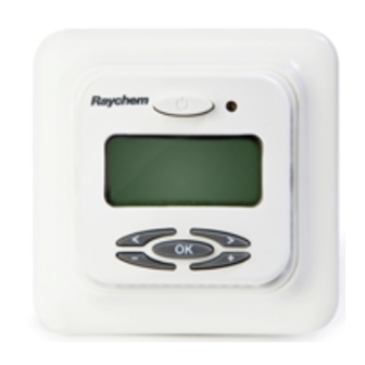
Page 6: Description
/ floor sensing mode / Room sensing mode with floor limiter) depending on your needs. Standby The NRG-Temp will switch on and off your underfloor heating in order to obtain the set-temperature. When the NRG-Temp is switching on the electrical... - Page 7 When nobody is present in the Temperature room, it would be a waste of energy to heat up the floor. In the EcoH or EcoO programs, the NRG-Temp is switching between the Reduced and the Comfort Temperature based on a weekly schedule.
-
Page 8: Mounting And Installation
±1,5 m Figure 3 If the NRG-Temp is mounted in a wall with a rough surface, e.g. bricks, use silicon glue to make a seal between the wall and the thermostat frame. Note: The NRG-Temp can also be mounted on a wall with a wall box. -
Page 9: Mounting The Floor Sensor
Figure 4 3.2 MOUNTING THE FLOOR SENSOR The floor sensor should be installed in a separate flexible conduit for easy replacement and in order to avoid signal disturbance resulting in a possible malfunction of the thermostat. For best control performance, position the floor sensor between two heating cables as close as possible to the top floor surface. -
Page 10: Connection Of The Thermostat To The Power Supply
3.3 CONNECTION OF THE THERMOSTAT TO THE POWER SUPPLY The thermostat must be connected to 230VAC according to the circuit diagrams (Figure 6). Direct connection – e.g. single heating circuit Heating cable Power supply Pilot wire Floor 230 VAC 230 VAC signal sensor Max.13A... -
Page 11: Product Specific Information
3.4 PRODUCT SPECIFIC INFORMATION 3.4.1 NRG-TEMP IN COMBINATION WITH T2QUICKNET HEATING MAT T2QuickNet heating mats are approved with the NRG-Temp thermostat working in floor sensor mode. Be aware that the floor sensor must be installed and activated for any installation with T2QuickNet. -
Page 12: Getting Started
4 GETTING STARTED When you switch on the NRG-Temp for the first time, the NRG-Temp will propose the Comfort program (Co flashing on the screen). • • • • • • • • • • • • • • •... - Page 13 5 NAVIGATION The NRG-Temp thermostat is designed to easily navigate through the different functions General principle: To use the NRG-Temp: • Navigate between functions using • Modify a setting using • Confirm your selection using • • • • •...
-
Page 14: Reduced Temperature
Function Symbol Display EcoOffice Booster EcoOffice Comfort Temperature (*) EcoHome Standby EcoHome • • • • • • • • • • • • • • • • Automatic EcoHome EcoHome Reduced Temperature (*) • • • • • • •... -
Page 15: Automatic
• • • • • to be in Comfort Temperature (see 6.3.2 for more explanation) EcoOffice EcoOffice EcoOffice Standby Note: When selecting “ ” the NRG-Temp will return • • • • • • • • • • • •... -
Page 16: In Economic Programs (Ecoh/Ecoo)
• • • • • • • • • • • Comfort temperature during a period of 2 hours. If you activate the Booster, your NRG-Temp thermostat EcoHome • • • • • • • • • • will be set for 2 hours to the Comfort Temperature + 5 degrees. -
Page 17: Program 1: Comfort (Co) R
• • • • • • • • • • • • • • • • • • • • • • • • • • • • • • • • • • • • • • • • •... -
Page 18: Program 3: Economic Office (Ecoo)
Factory settings: • Comfort Temperature ( ) = 23°C EcoHome EcoHome • Reduced Temperature ( ) = 16°C 6.6.3 PROGRAM 3: ECONOMIC OFFICE (EcoO) • • • • • • • • • • • • • • • • •... -
Page 19: Programming
• • • • • • • • • • • • • • • • • • • • • • • • • • • • • • • • • • • • Figure 15 • • •... -
Page 20: The Standard User Menus
Step 3. Programming Day 1 Step 3.A. Programming the first timeslot of that day • • • • • • • • • • • • • • • • You can now select the Comfort “ ” or Reduced EcoHome “... -
Page 21: User Menu 1: Sensor Setting
EcoOffice • • • • • • • • • • • • • • • • Standby • • • • • • • • • • • • • • • • EcoOffice 3: Calibration of the floor sensor temperature EcoHome •... -
Page 22: User Menu 2: Service Read Out
• • • • • • • • • • • • • • • • • • • • • • • • • • 7.1.2 USER MENU 2: SERVICE READ OUT • • • The Service read out gives you the possibility to see the actual temperature measured by the sensors (floor sensor = T and room sensor = T... -
Page 23: Floor Temperature (Offset Value)
7.1.3 USER MENU 3: CALIBRATION OF THE FLOOR TEMPERATURE (OFFSET VALUE) To adjust the floor-sensor temperature to the real conditions of the floor surface, you can make an OFFSET to the temperature measured by the floor see User Menu 2: Service read out). sensor (T floor Use a separate thermometer that you position... -
Page 24: User Menu 7: Maximum Temperature Set Point For The Floor Sensor
7.1.5 USER MENU 5: DISPLAY BACK-LIGHT “ON” • • DURATION The display of the NRG-Temp is lid up every time you touch one of the buttons. After 30 seconds Standby the display light is turned off again. You can adapt the duration of the display lighting in this menu. -
Page 25: User Menu 8: Minimum Temperature Set Point For The Room Sensor
Factory set value: The factory value is depending on the active sensing mode: • In floor sensing mode = 35°C • In room sensing mode = 27°C • In room sensing mode with floor limiter = 27°C EcoHome 7.1.8 USER MENU 8: MINIMUM TEMPERATURE SET POINT FOR THE ROOM SENSOR •... -
Page 26: Menus
First Warming function to help warming up the screed gradually over 21 days. When the function is active, you cannot use the NRG-Temp for anything else than for this function. The display will show the day countdown during the complete first warming function. - Page 27 7.2.5 USER MENU E: DELAYED START-UP When starting up the NRG-Temp in Comfort program after a power interruption, it can be interesting to start different heating circuits separately. You can set a delay on the start-up of each thermostat by using the delayed start-up function.
- Page 28 • • • • • • • • • • • • • • • It is possible to lock the keys of the NRG-Temp thermostat. • • • • • • • • • • • • • •...
-
Page 29: Trouble Shooting
Table 6 Note: Some basic BMS systems can only generate the signals for -3.5°C (adaptable in menu H). EcoHome EcoHome When the NRG-Temp gets an input from the BMS system, the symbol P appears on the screen. • • • •... -
Page 30: Hysteresis
11 TECHNICAL SPECIFICATION Supply voltage 230VAC, +10%, –15%, 50/60 Hz Power consumption, average 4 VA Main power switch 2-pole Relay output 230V, max. 13A Ambient temperature – operation 0 +40°C Ambient temperature – transport –20 +50°C Protection class IP 21 Terminals Max. -
Page 31: Approvals And Declarations
12 APPROVALS AND DECLARATIONS 210116... - Page 32 Tel. +47 66 81 79 90 Fax +47 66 80 83 92 salesno@pentair.com WWW.PENTAIRTHERMAL.COM All Pentair trademarks and logos are owned by Pentair or its global affiliates. Pentair reserves the right to change specifications without prior notice. © 2014 Pentair. THERMAL BUILDING SOLUTIONS...
Need help?
Do you have a question about the NRG-Temp and is the answer not in the manual?
Questions and answers