Toshiba RAS-10JKVP-E Service Manual
Split type
Hide thumbs
Also See for RAS-10JKVP-E:
- Owner's manual (31 pages) ,
- Installation manual (20 pages) ,
- Service manual (13 pages)

Subscribe to Our Youtube Channel
Related Manuals for Toshiba RAS-10JKVP-E


Summary of Contents for Toshiba RAS-10JKVP-E
- Page 1 .ILE NO. A02-015 SPLIT TYPE RAS-10JKVP-E RAS-10JAVP-E RAS-13JKVP-E RAS-13JAVP-E PRINTED IN JAPAN, Mar.,2002 ToMo...
-
Page 2: Table Of Contents
CONTENTS 1. SPECIFICATIONS ..................3 2. REFRIGERANT R410A ................5 3. CONSTRUCTION VIEWS ................ 13 4. WIRING DIAGRAM .................. 15 5. SPECIFICATIONS OF ELECTRICAL PARTS ......... 17 6. REFRIGERANT CYCLE DIAGRAM ............18 7. CONTROL BLOCK DIAGRAM ..............20 8. OPERATION DESCRIPTION ..............22 9. -
Page 3: Specifications
1. SPECIFICATIONS 1-1. Specifications RAS-10JKVP-E/RAS-10JAVP-E, RAS-13JKVP-E/RAS-13JAVP-E Unit model Indoor RAS-10JKVP-E RAS-13JKVP-E Outdoor RAS-10JAVP-E RAS-13JAVP-E Current limited — — Cooling capacity (kW) Cooling capacity range (kW) 0.6–3.4 0.6–4.2 Heating capacity (kW) Heating capacity range (kW) 0.6–6.2 0.6–6.6 Power supply 1Ph/50Hz/220–240 V, 1PH/60Hz/220 V... - Page 4 Pipe length : 5m Pipe length : 5m –15 –10 –5 43 44 45 46 Outdoor temp. (˚C) Outdoor temp. (˚C) Capacity ratio : 100% = 3.5 kW (RAS-13JKVP-E) Capacity ratio : 100% = 2.5 kW (RAS-10JKVP-E) – 4 –...
-
Page 5: Refrigerant R410A
2. REFRIGERANT R410A This air conditioner adopts the new refrigerant HFC (6) When an air conditioning system charged with a (R410A) which does not damage the ozone layer. large volume of refrigerant is installed in a small room, it is necessary to exercise care so that, The working pressure of the new refrigerant R410A even when refrigerant leaks, its concentration is 1.6 times higher than conventional refrigerant... - Page 6 Table 2-2-1 Thicknesses of annealed copper pipes Thickness (mm) Nominal diameter Outer diameter (mm) R410A 6.35 0.80 0.80 9.52 0.80 0.80 12.70 0.80 0.80 15.88 1.00 1.00 (2) Joints b) Socket Joints For copper pipes, flare joints or socket joints are Socket joints are such that they are brazed used.
- Page 7 d) Flare Processing Make certain that a clamp bar and copper pipe have been cleaned. ØD By means of the clamp bar, perform the flare processing correctly. Use either a flare tool for R410A or conven- tional flare tool. Flare processing dimensions differ according to the type of flare tool.
- Page 8 Table 2-2-6 Flare and flare nut dimensions for R22 Outer Dimension (mm) Flare nut Nominal Thickness diameter width diameter (mm) (mm) (mm) 6.35 9.52 13.0 13.5 12.70 16.2 16.0 12.9 15.88 19.7 19.0 16.0 19.05 23.3 24.0 19.2 Fig. 2-2-2 Relations between flare nut and flare seal surface (2) Flare Connecting Procedures and Precautions When it is strong, the flare nut may crack and may be made non-removable.
- Page 9 2-3. Tools 2-3-1. Required Tools The service port diameter of packed valve of the outdoor unit in the air conditioner using R410A is changed to prevent mixing of other refrigerant. To reinforce the pressure-resisting strength, flare processing dimensions and opposite side dimension of flare nut (For Ø12.7 copper pipe) of the refrigerant piping are lengthened. The used refrigerating oil is changed, and mixing of oil may cause a trouble such as generation of sludge, clogging of capillary, etc.
-
Page 10: Recharging Of Refrigerant
2-4. Recharging of Refrigerant When it is necessary to recharge refrigerant, charge the specified amount of new refrigerant according to the following steps. Recover the refrigerant, and check no refrigerant remains in the equipment. When the compound gauge’s pointer has indicated –0.1 Mpa (–76 cmHg), place the handle Low in the fully closed position, and turn off the vacuum pump’s power switch. -
Page 11: Brazing Of Pipes
(1) Be sure to make setting so that liquid can be charged. (2) When using a cylinder equipped with a siphon, liquid can be charged without turning it upside down. It is necessary for charging refrigerant under condition of liquid because R410A is mixed type of refrigerant. Accordingly, when charging refrigerant from the refrigerant cylinder to the equipment, charge it turning the cylinder upside down if cylinder is not equipped with siphon. - Page 12 (2) Characteristics required for flux 2-5-3. Brazing • Activated temperature of flux coincides with As brazing work requires sophisticated techniques, the brazing temperature. experiences based upon a theoretical knowledge, it must be performed by a person qualified. • Due to a wide effective temperature range, flux is hard to carbonize.
-
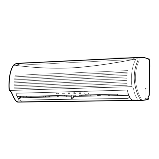
Page 13: Construction Views
3. CONSTRUCTION VIEWS 3-1. Indoor Unit RAS-10JKVP-E, RAS-13JKVP-E Indoor heat exchanger Air filter Indoor air suction port Front panel Suction grille Power supply cord Knockout system Knockout system nstallation plate hanging section Auxiliary hose (Outside length: 0.45m) Flare Ø6.35 nstallation plate... - Page 14 3-2. Outdoor Unit RAS-10JAVP-E, RAS-13JAVP-E A leg part Ø11 x 17U-shape hole Ø25 drain hole (For Ø8-Ø10 anchor bolt) 8-Ø6 hole (For fixing outdoor unit) B leg part Ø11 x 17 long hole (For Ø8-Ø10 anchor bolt) Ø4.5 embossing (Ø4STS used) (For sunshade roof attaching) Valve cover Fan guard...
-
Page 15: Wiring Diagram
4. WIRING DIAGRAM 4-1. Indoor Unit RAS-10JKVP-E, RAS-13JKVP-E OUTDOOR TERMINAL BLOCK INDOOR 1 2 3 4 TERMINAL BLOCK 1 2 3 4 Heat exchanger GRN & YEL 1 2 3 4 WHI BLK Ion electride CN01 1 2 3 4... - Page 16 4-2. Outdoor Unit RAS-10JAVP-E, RAS-13JAVP-E PULSE MODULATING VALVE COIL for 4-WAY VALVE THERMOSTAT COMPRESSOR CN600 CN601 CN602 CN603 CN701 CN703 CN500 SURGE ABSORBER POWER SUPPLY RELAY 220-240V~, 50Hz REACTOR VARISTOR 220V~, 60Hz FUSE T25A INDOOR UNIT POEWR RELAY C12 C13 C14 ELECTRONIC STARTER FUSE...
-
Page 17: Specifications Of Electrical Parts
5. SPECIFICATIONS OF ELECTRICAL PARTS 5-1. Indoor Unit RAS-10JKVP-E, RAS-13JKVP-E Parts name Type Specifications Fan motor (for indoor) MF-280-30-1 DC280–340V, 30W Thermo. sensor (TA-sensor) ( – ) 10kΩ at 25°C Heat exchanger temp. sensor ( – ) 10kΩ at 25°C... -
Page 18: Refrigerant Cycle Diagram
6. REFRIGERANT CYCLE DIAGRAM 6-1. Refrigerant Cycle Diagram RAS-10JKVP-E/RAS-10JAVP-E RAS-13JKVP-E/RAS-13JAVP-E Temp. measurement INDOOR UNIT Indoor heat exchanger Cross flow fan Max. : 15m Pressure measurement Deoxidized copper pipe Chargeless : 15m Gauge attaching port Outer dia. : 6.35mm Vacuum pump connecting port Thickness : 0.8mm... -
Page 19: Operation Data
6-2. Operation Data <Cooling> Temperature Heat exchanger Model Standard Compressor condition (°C) pipe temp. Indoor fan Outdoor fan name pressure revolution mode mode RAS- P (MPa) (rps) Indoor Outdoor T1 (°C) T2 (°C) 10JKVP-E 0.9 to 1.1 12 to 14 41 to 43 High High... -
Page 20: Control Block Diagram
7. CONTROL BLOCK DIAGRAM 7-1. Indoor Unit Indoor Unit Control Panel RAS-10JKVP-E, RAS-13JKVP-E M.C.U Heat Exchanger Sensor(Tc) Functions Louver Motor • Cold draft preventing Function Temperature Sensor(Ta) • 3-minute Delay at Restart for Compressor Louver Motor Infrared Rays Signal Receiver... - Page 21 MICRO-COMPUTER BLOCK DIAGRAM For INDOOR UNIT 220–240 V/50Hz 220 V/60Hz MCC813 (P.C.B) OUTDOOR UNIT Indoor unit Rotor position send/receive detect circuit M.C.U circuit • PWM synthesis function Rotor position detect circuit • Input current release control • IGBT over-current detect control Discharge Gate drive •...
-
Page 22: Operation Description
8. OPERATION DESCRIPTION • Detection of inverter input current and current 8-1. Outline of Air Conditioner Control release operation This air conditioner is a capacity-variable type air • Over-current detection and prevention operation conditioner, which uses DC motor for the indoor fan to IGBT module (Compressor stop function) motor and the outdoor fan motor. - Page 23 8-2. Operation Description Item Operation flow and applicable data, etc. Description 1. Basic 1) Operation control 1) The operation conditions are operation selected by the remote controller as Receiving the user’s operation condition setup, the opera- shown in the left. tion statuses of indoor/outdoor units are controlled.
- Page 24 Item Operation flow and applicable data, etc. Description 1. Basic operation 3) AUTO operation 1) Detects the room temperature (AUTO operation removes troubles in setting up the (Ta) when the operation started. operation mode for cooling/heating operation.) 2) Selects an operation mode from Selection of operation mode Ta in the left figure.
- Page 25 *5 : No. of revolution = +1.0 (M + –L) x 1/4 + L +0.5 (Linear approximation L(W6) from M+ and -L) (Table 1) Tap allocation of indoor fan air volume RAS-10JKVP-E RAS-13JKVP-E Air volume COOL HEAT No. of revolution Air volume No. of revolution...
- Page 26 Item Operation flow and applicable data, etc. Description 2. Indoor fan <In heating operation> 1) When setting the air volume to motor control M, M+, L, L-, or H on the remote controller, the operation is HEAT ON performed with the constant air volume of the air volume level shown in Fig.
- Page 27 Item Operation flow and applicable data, etc. Description 3. Outdoor fan The blowing air volume at the outdoor unit side is controlled. 1) The operation command sent motor control from the remote controller is Receiving the operation command from the controller at processed by the indoor unit indoor side, the controller at outdoor side controls No.
- Page 28 Item Operation flow and applicable data, etc. Description 4. Capacity The cooling or heating capacity corresponding to the load is 1) The difference between tempera- control adjusted. ture set on remote controller (Ts) and temperature of indoor unit According to difference between the setup value of tempera- (Ta) is detected.
- Page 29 Item Operation flow and applicable data, etc. Description 6. Release <In cooling/dry operation> 1) When temperature of the indoor protective (Freeze proof for indoor heat exchanger) heat exchanger is down to 5°C or control by lower, No. of revolution of the In cooling/dry operation, the sensor of indoor heat ex- temperature of compressor is decreased.
- Page 30 Item Operation flow and applicable data, etc. Description 7. Quick heating This function quickens the starting of heating operation When the following conditions are control when indoor/outdoor temperature is low. satisfied, winding is heated by output (Effective only in heating operation) varied by the outdoor heat exchanger temperature.
- Page 31 Item Operation flow and applicable data, etc. Description 9. Louver control This function controls the air direction of the indoor unit. 1) Louver • The position is automatically controlled according to the operation position mode (COOL/HEAT). • The set louver position is stored in memory by the microcomputer, and the louver returns to the stored position when the next operation is performed.
- Page 32 Item Operation flow and applicable data, etc. Description 10. ECO When pushing [ECO] button on the remote controller, a quiet operation and mild operation is performed by decreasing the air volume and No. of revolution of the compressor. <Cooling operation> <Cooling operation>...
- Page 33 Item Operation flow and applicable data, etc. Description 11. Forced A forced operation is performed for refrigerant recovery, etc. 1) When pushing [RESET] button, operation when reinstalling the air conditioner. the forced [AUTO mode] opera- tion starts. Pushing [RESET] button starts the forced operation of [AUTO] operation.
- Page 34 Item Operation flow and applicable data, etc. Description 12. Air filtering This function generates minus ion while cleaning the air Operation button control in the room. Present If Filter-ON signal is received while the air conditioner PAP button Air conditioner status stops, the filter starts operation, and if it is received Stop...
- Page 35 Item Operation flow and applicable data, etc. Description 14. Pulse motor This function controls throttle amount of the refrigerant in 1) When starting the operation, move valve (PMV) the refrigerating cycle. the valve once until it fits to the control stopper.
- Page 36 8-3. Temporary Operation • Temporary Auto operation, existence of Auto Restart, and Temporary Cooling operation can be set by the RESET button of the indoor controller. Fig. 8-3-1 Table 8-3-1 RESET button Control OFF → ON Temporary Auto operation start After pushing button Auto Restart control select for 3 seconds...
- Page 37 8-4. Auto Restart Function 8-4-1. How to Set the Auto Restart Function To set the auto restart function, proceed as follows: This indoor unit is equipped with an automatic restarting function which allows the unit to restart The power supply to the unit must be on ; the operating with the set operating conditions in the function will not set if the power is off.
- Page 38 8-4-2. How to Cancel the Auto Restart Function To cancel auto restart function, proceed as follows : Repeat the setting procedure : the unit receives the signal and beeps three times. The unit will be required to be turned on with the remote controller after the main power supply is turned off. •...
-
Page 39: Remote Controller And Its Fuctions
8-6. Remote Controller and Its Fuctions Memory button (MEMO) Push this button to ready for storing the settings. 8-6-1. Parts Name of Remote Controller Hold down the button for more than 3 seconds to store the setting indicated on the remove control and Infrared signal emitter until the mark is displayed. - Page 40 8-6-2. Name and Functions of Indications on Remote Controller [Display] All indications, except for the clock time indicator, are displayed by pushing the button. Transmission mark TIMER and clock time display This transmission mark indicates when the The time setting for timer operation or the clock remote controller transmits signals to the indoor time is indicated.
- Page 41 8-7. Hi-POWER Mode ([Hi-POWER] button on the remote controller is pushed.) When [Hi-POWER] button is pushed while the indoor unit is in Auto, Cooling or Heating operation, Hi- POWER mark is indicated on the display of the remote controller and the unit operates as follows. (1) Automatic operation •...
-
Page 42: Installation Procedure
9. INSTALLATION PROCEDURE 9-1. Safety Cautions For general public use Power supply cord of outdoor unit shall be more than 1.5mm² (H07RN-F or 245IEC66) polychloroprene sheathed flexible cord. CAUTION New Refrigerant Air Conditioner Installation • THIS AIR CONDITIONER ADOPTS THE NEW HFC REFRIGERANT (R410A) WHICH DOES NOT DESTROY OZONE LAYER. - Page 43 • Appliance shall be installed in accordance with national wiring regulations. If you detect any damage, do not install the unit. Contact your Toshiba dealer immediately. WARNING • Exposure of unit to water or other moisture before installation may result in an electrical short. Do not store in a wet basement or expose to rain or water.
-
Page 44: Installation Diagram Of Indoor And Outdoor Units
9-1-1. Installation Diagram of Indoor and Outdoor Units For the rear left and left piping Before installing the wireless remote controller • With the remote controller Wall cover removed, correctly 67 mm or more load the figure, supplied batteries while observing Insert the cushion between Hook 140 mm... - Page 45 9-1-3. Accessory and Installation Parts Part No. Part No. Part No. Part name (Q'ty) Part name (Q'ty) Part name (Q'ty) Mounting screw Ø4 x 25L x 6 Installation plate x 1 Remote controller holder x 1 Wireless Flat head wood screw remote controller x 1 Zeolite-plus filter x 1 Ø3.1 x 16L x 2...
-
Page 46: Indoor Unit
9-2. Indoor Unit Mounting the Installation Plate For installation of the indoor unit, use the paper 9-2-1. Installation Place pattern on the back. • A place which provides the spaces around the indoor unit as shown in the above diagram. •... - Page 47 9-2-3. Electrical Work Terminal block Screw Cord clamp Terminal cover 1. The supply voltage must be the same as the rated Connecting voltage of the air conditioner. cable 2. Prepare the power source for exclusive use with the air conditioner. NOTE : •...
- Page 48 How to install the Drain Cap Left-hand connection with piping Firmly insert drain hose connecting part unit hitting on Bend the connecting pipe so that it is laid within 43mm a heat insulator. above the wall surface. If the connecting pipe is laid exceeding 43mm above the wall surface, the indoor unit may unstably be set on the wall.
- Page 49 9-2-6. Indoor Unit Installation 9-3. Outdoor Unit 1. Pass the pipe through the hole in the wall, and hook 9-3-1. Installation Place the indoor unit on the installation plate at the upper hooks. • A place which provides the spaces around the outdoor unit as shown in the left diagram.
- Page 50 2. Insert a flare nut into the pipe, and flare the pipe. 9-3-3. Evacuating • Projection margin in flaring : A (Unit : mm) After the piping has been connected to the indoor unit, Rigid (Clutch type) you can perform the air purge together at once. Outer dia.
- Page 51 Fig. 9-3-9 9-3-6. Test Operation To test the system, push and hold RESET button for Model RAS-10JKVP-E RAS-13JKVP-E 10 sec. (There will be one short beep.) 220 – 240 V~, 50 Hz Power source 220 V~, 60 Hz...
-
Page 52: How To Diagnose The Trouble
10. HOW TO DIAGNOSE THE TROUBLE The pulse modulating circuits are mounted to both NOTE : indoor and outdoor units. Therefore, diagnose A large-capacity electrolytic capacitor is used in the troubles according to the trouble diagnosis proce- outdoor unit controller (inverter). Therefore, if the dure as described below. - Page 53 10-1-3. Operation Which is not a Trouble (Program Operation) For controlling the air conditioner, the program operations are built in the microcomputer as described in the following table. If a claim is made for running operation, check whether or not it meets to the contents in the following table.
-
Page 54: Judgment By Flashing Led Of Indoor Unit
10-3. Judgment by Flashing LED of Indoor Unit While the indoor unit monitors the operation status of the air conditioner, if the protective circuit operates, the contents of self-diagnosis are displayed with block on the indoor unit indication section. Table 10-3-1 Check Item Block display... - Page 55 10-4. Self-Diagnosis by Remote Controller (Check Code) (1) If the lamps are indicated as shown B to H in Table 10-3-1, excute the self-diagnosis by the remote control- ler. (2) When the remote controller is set to the service mode, the indoor controller diagnoses the operation condi- tion and indicate the information of the self-diagnosis on the display of the remote controller with the check codes.
- Page 56 10-4-2. Caution at Servicing (1) After servicing, push the START/STOP button to return to the normal mode. (2) After servicing by the check code, turn off breaker of the power supply, and turn on breaker of the power supply again so that memory in the microcomputer returns the initial status. However, the check codes are not deleted even if the power supply is turned off because they are stored in the fixed memory.
- Page 57 Block distinction Operation of diagnosis function Judgment and action Check Check Block Cause of operation conditioner Remarks code code status Outdoor P.C. Inverter over-current All off Displayed when Even if trying operation again, all board protective circuit error is detected. operations stop immediately.
-
Page 58: Judgment Of Trouble By Every Symptom
10-5. Judgment of Trouble by Every Symptom 10-5-1. Indoor Unit (Including Remote Controller) (1) Power is not turned on (Does not operate entirely) <Primary check> 1. Is the supply voltage normal? Operation 2. Is the normal voltage provided to the outdoor unit? 3. - Page 59 (3) Only the indoor motor fan does not operate <Primary check> ‚ 1. Is it possible to detect the power supply voltage (200–240V) between on the terminal block? 2. Does the indoor fan motor operate in cooling operation? (In heating operation, the indoor fan motor does not operate for approximately 5 minutes after it is turned on, to prevent a cold air from blowing in.) Turn off power supply once, and...
- Page 60 (4) Indoor fan motor automatically starts to rotate by turning on power supply <Cause> The IC is built in the indoor fan motor. Therefore the P .C. board is also mounted to inside of the motor. If the P .C. board is soldered imperfectly or the IC is defective, the fan motor may automatically rotate by turning on power supply.
- Page 61 (5) Troubleshooting for remote controller <Primary check> Check that A or B selected on the main unit is matched with A or B selected on the remote controller. The unit does not beep at all. Push the START/STOP button. Operation lamp on indoor unit is not indicated.
- Page 62 10-5-2. Wiring Failure (Interconnecting and Serial Signal Wire) (1) Outdoor unit does not operate ‚ ƒ 1) Is the voltage between of the indoor terminal block varied? Confirm that transmission from indoor to outdoor is correctly performed based upon the following dia- gram.
- Page 63 10-6. Check Code 1C (Miswiring in indoor/outdoor units) and 1E <Check procedure> Gas leakage, Discharge temp. error, disconnection of TS/TC gas leakage sensors (Check code 02, 1C) (Check code 03, 1E) Valve drive check Is coil of the pulse modulation valve Set it correctly.
-
Page 64: Troubleshooting
10-7. Troubleshooting 10-7-1. How to Check Whether the Air Filter is Good or Not Turn off the power breaker once, and turn on again after 10 seconds. Does the operation lamp flash? To item “Power supply is not turned on” Turn off the power breaker and remove CN34 (Micro switch connector). - Page 65 10-7-2. How to Check Whether the Minus Ion Generator is Good or Not Turn off the power breaker once, and turn on again after 10 seconds. Does the operation lamp flash? To item “Power supply is not turned on” Turn off the power breaker and remove CN34 (Micro switch connector).
-
Page 66: How To Diagnose Trouble In Outdoor Unit
10-8. How to Diagnose Trouble in Outdoor Unit 10-8-1. Summarized Inner Diagnosis of Inverter Assembly Table 10-8-1 Diagnosis/Process flowchart Item Contents Summary Preparation Turn “OFF” the power breaker, and remove 3P connector which connects inverter and Remove connector of compressor. compressor. - Page 67 Diagnosis/Process flowchart Item Contents Summary Check Check winding resistance between phases of compres- sor, and resistance between outdoor frames by using a tester. → OK if 10MΩ or more Check • Is not grounded. winding of • Is not short-circuited →...
- Page 68 (3) Check procedures Table 10-9-1 Procedure Check points Causes Turn off the power supply and Check whether or not the fuse Impulse voltage was applied or the remove the P .C. board assembly (F01) is blown. indoor fan motor short-circuited. from electronic parts base.
- Page 69 10-9-2. P.C. Board Layout +12V Bottom View (For the Top View, refer to page 65.) [1] Sensor characteristic table TD : Discharge temp. sensor TA : Room temp. sensor TC : Heat exchanger temp. sensor TO : Outdoor temp. sensor TA, TC, TO, TE, TS TE : Outdoor heat exchanger temp.
- Page 70 10-9-3. Indoor Unit (Other Parts) Part name Checking procedure Room temp. (TA) sensor Disconnect the connector and measure the resistance value with Heat exchanger (TC) sensor tester. (Normal temp.) Temperature 10°C 20°C 25°C 30°C 40°C Sensor TA, TC (kΩ) 20.7 12.6 10.0 Remote controller...
- Page 71 10-9-5. Checking Method for Each Part Part name Checking procedure Electrolytic capacitor 1. Turn OFF the power supply breaker. (For raising pressure, 2. Discharge all three capacitors completely. smoothing) 3. Check that safety valve at the bottom of capacitor is not broken. 4.
-
Page 72: How To Simply Judge Whether Outdoor Fan Motor Is Good Or Bad
10-10. How to Simply Judge Whether Outdoor Fan Motor is Good or Bad 1. Symptom • Outdoor fan motor does not rotate. • Outdoor fan motor stops within several tens seconds though it started rotating. • Outdoor fan motor rotates or does not rotate according to the position where the fan stopped, etc. Remote controller check code “02 : Outdoor block, 1A : Outdoor fan drive system error”... -
Page 73: How To Replace The Main Parts
11. HOW TO REPLACE THE MAIN PARTS 11-1. Indoor Unit Part name Procedures Remarks Front panel 1) Stop operation of the air conditioner and turn off Installation its main power supply. board Front panel 2) Push “PUSH” part under the front panel and remove hooks of the front panel from the installation board. - Page 74 Part name Procedures Remarks „ ‚ Heat exchanger 1) Follow to the procedure in the above item 2) Remove the cable holder from the rear side of the main unit. 3) Remove two fixing screws at the left side of Cable holder the end plate of the heat exchanger.
- Page 75 Part name Procedures Remarks ‡ Drift fan 1) Stop operation of the air conditioner and turn off its main power supply. ‚ 2) Follow to the procedure in the item 3) Remove two fixing screws at the left side of the end plate of the heat exchanger, and remove Rear side of mains two fixing screws of the bearing base.
- Page 76 Part name Procedures Remarks ‡ Drift fan • Caution at reassembly a) At assembling work of the bearing base, check that the drain pipe is surely incorporated in the rear plate. Drain pipe (Otherwise, water leak is caused.) b) To incorporate the fan motor, remove the fan motor rubber (at shaft core side), incorporate the motor into the position in the following figure, and then install the fan motor.
- Page 77 11-2. How to replace the parts of electric dust collector (Be sure to pull off the power plug before work.) Part name Procedures Remarks Electric dust 1) Remove the front panel. ( Front panel) Connector collector 2) Remove a fixing screw and a connector. 3) Remove the minus ion generator.
- Page 78 11-3. Microcomputer Part name Procedure Remarks Common procedure 1) Turn the power supply off to stop the Replace the thermal fuse, operation of air-conditioner. terminal block, microcomputer ass’y and the P .C. board ass’y. 2) Remove the front panel. •...
- Page 79 11-4. Outdoor Unit Table-11-4-1 Part name Procedure Remarks 1. Detachment Common procedure 1) Stop operation of the air conditioner, and turn Upper cabinet off the main switch of the breaker for air condi- tioner. Wiring cover 2) Remove the valve cover. (ST1TØ4 x 10 1 pc.) Valve •...
- Page 80 Part name Procedure Remarks ƒ Inverter 1. Detachment Inverter cover P . C. board assembly (Soldered surface) 1) Perform work of item 1 of 2) Remove screw (ST1TØ4 x 10 2 pcs.) of the upper part of the front cabinet. •...
- Page 81 Part name Procedure Remarks „ Control board 1) Disconnect lead wires and connectors con- assembly nected from the control board assembly to other parts. CN701 CN703 CN602 CN301 CN500 1. Lead wires Lead wires Lead wires Lead CN603 wires CN601 CN600 CN300 •...
- Page 82 Part name Procedure Remarks † ‚ Fan motor 1) Perform work of item 1 of 2) Remove the flange nut fixing the fan motor and Fan motor the propeller. Propeller fan • Flange nut is loosened by turning clockwise. (To tighten the flange nut, turn counterclock- wise.) 3) Remove the propeller fan.
- Page 83 Part name Procedure Remarks ‰ Pulse 1. Detachment modulating ‚ ƒ … 1) Perform work of item 1 of , and valve coil 2) Turn the coil clockwise (counterclockwise) by 90 degrees, and remove coil from the pulse modulat- ing valve.
- Page 84 Part name Procedure Remarks Replacement of 1) Cut the sensor 100 mm longer than old one. temperature 2) Cut the protective tube after pulling out it Cutting here sensor for (200 mm). Thermal Connector sensor part servicing only 3) Move the protective tube toward the thermal sensor side and tear the tip of lead wire in Common service two then strip the covering part.
- Page 85 MCC-813 – 85 –...
-
Page 86: Exploded Views And Parts List
12. EXPLODED VIEWS AND PARTS LIST 12-1. Indoor Unit (1) – 86 –...
Need help?
Do you have a question about the RAS-10JKVP-E and is the answer not in the manual?
Questions and answers