
Subscribe to Our Youtube Channel
Related Manuals for SII MP-A40 SERIES


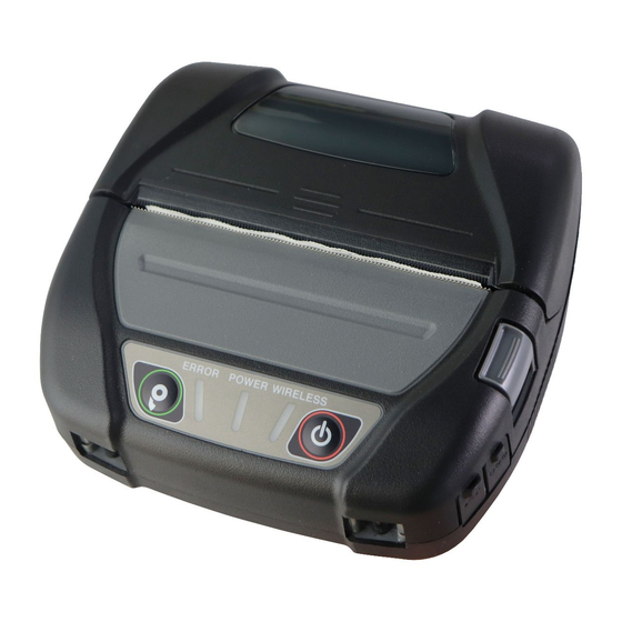
Summary of Contents for SII MP-A40 SERIES
- Page 1 USER'S GUIDE Thermal Printer MP-A40 SERIES Read this USER'S GUIDE carefully before using the printer. Keep this USER'S GUIDE in a place where it can be accessed quickly.
- Page 2 Copyright 2016 by Seiko Instruments Inc. All rights reserved. The information contained herein is the property of SII and shall not be reproduced in whole or in part without prior written approval of SII. SII reserves the right to make changes in the specifications and materials contained herein without notice and shall not be responsible for any damages (including consequential) caused by reliance on the materials presented, including but not limited to typographical, arithmetic, and listing errors.
- Page 3 Product: AC adapter PW-D0940-W2 Directive: Title 2014/30/EU EC Electromagnetic Compatibility Directive 2014/35/EU EC Low Voltage Directive 2011/65/EU Restriction of the use of certain hazardous substances (RoHS) Directive Standards EN 55022 Class B EN 61000-3-2 EN 61000-3-3 EN 55024 EN 60950-1 EN 50581 Product: Battery Charger PWC-A071-A1...
-
Page 4: Table Of Contents
Keep this manual in a place where it can be accessed quickly. See ”MP-A40 SERIES THERMAL PRINTER TECHNICAL REFERENCE” for more detailed function and specifications on the printer. This USER'S GUIDE consists of the following sections. -
Page 5: Safety Precautions
2. SAFETY PRECAUTIONS In this SAFETY PRECAUTIONS, the following symbols are used to ensure safe and proper use of products and prevent from damaging devices. WARNING Failure to follow the instructions marked with this symbol could result in severe personal injury or death. CAUTION Failure to follow the instructions marked with this symbol could result in minor personal injury or property damage. - Page 6 OPERATING PRECAUTIONS The "products" shall collectively mean printer, battery pack, AC adapter, AC cable, car charger, and battery charger. WARNING Never attempt the followings. Failure to follow the instructions leads to fire, electric shock, or accident. DO NOT disassemble or reconstruct the products. Take care not to spill liquid on the products.
- Page 7 Be sure to charge the battery pack under the specified temperature range. It may cause leakage, overheating, rupture or fire. DO NOT expose the battery pack in a fire and heat it. To avoid liquid leakage, overheat, rapture or fire, DO NOT leave battery pack under high temperature conditions such as in scorching heat, inside a car, or near a fire.
- Page 8 Procedures to take when in trouble Follow the instructions in the following cases. Failure to follow the instructions may lead to fire, electric shock, or accident. Turn off the printer, and unplug the AC plug from an outlet in any of the following cases. (In case of using the car charger, unplug the cigar plug from a car accessory socket.) And then, remove the battery pack.
- Page 9 Observe the following instructions. Failure to follow the instructions may lead fire, electric shock, or accident. Turn off the products and unplug the AC plug from an outlet when not in use for a long time or before maintenance. And remove the battery pack from the printer or battery charger. DO NOT use or store the products in the following locations: Locations exposed to direct sunlight or high temperature such as in a car.
-
Page 10: Operating Precautions
20%RH to 80%RH (0°C to 40°C) (Non condensing) Refer to "MP-A40 SERIES THERMAL PRINTER TECHNICAL REFERENCE" for the certifiable humidity range at each temperature. DO NOT install the products near devices that generate strong electromagnetic fields such as a ◆... - Page 11 Even if the printer connects with the AC adapter during printing or transmission powered by the ◆ battery pack, a power supply will be continued from the battery pack until its job is completed. If the printer suspends printing because the battery remaining capacity becomes low, connect AC adapter and restart printing or transmission.
-
Page 12: Precautions For Maintenance
DO NOT cut except liner part of a label sheet with the paper cutter. This instruction may make the ◆ cutting edge dull due to label sheet adhesive sticking to the cutter. The car charger is only for charging. Even if the car charger is connected to the printer, the printer ◆... -
Page 13: Precautions On Discarding
Precautions for storing Turn off the power when not in use. ◆ In addition, when the printer is not used for a long time, ・Unplug the AC plug from an outlet. ・Remove the battery pack from the printer. If not, it may cause overdischarge, the battery pack is not available for use even if it is charged. -
Page 14: Preparation
4. PREPARATION Make sure that the printer and its accessories are contained. Keep the package and packing materials for future transportation or long-term storage. Belt Clip Printer Partition Plate Partition Plate Partition Plate Attachment 80 Attachment 100 CD-ROM Safety Precautions: 1set (User Guide / Related Software) (3 sheets) - Page 15 The available accessories are shown below. See "20 SPECIFICATION" and "21 ACCESSORIES AND CONSUMABLE PARTS", and be sure to purchase our specified products listed on these references. AC Cable AC Adapter USB Interface Cable Battery Pack Battery Charger Car Charger Shoulder Strap Quad Battery Charger...
-
Page 16: Identifying The Model Type
5. IDENTIFYING THE MODEL TYPE The printer model is identified as follows: MP-A40-x06JK1x Series Name Interface Bluetooth + USB Wireless LAN + USB Countries* USA, Canada EU, EFTA, Turkey Japan Brazil *: Wireless LAN model only. -
Page 17: Each Part Of Printer
6. EACH PART OF PRINTER... - Page 18 1 POWER Switch 10 Paper outlet The POWER Switch turns the power on or off. Thermal paper is ejected from here. Two paper The POWER LED lights when turning on the cutters are installed: one is on the printer side, power.
-
Page 19: Led Display Of Printer
7. LED DISPLAY OF PRINTER LED Display of Printer The three LEDs of the printer show their status. • ERROR LED and POWER LED Table 7-1 Printer Status • WIRELESS LED Table 7-2 Bluetooth / Wireless LAN Status Table 7-1 Printer Status ERROR LED POWER LED Description... - Page 20 Table 7-2 Bluetooth / Wireless LAN Status WIRELESS LED Wireless Communication Status Lighting Color Pattern Wireless off Connecting Blue No-connecting Blue Blink-2 Initializing wireless communication Blue Blink-4 In paring mode* Blue Blink-3 *: Only Bluetooth model and when its Inquiry Response in the Function Setting is set to "Pairing Mode". Table 7-3 Blink Pattern Status Pattern...
- Page 21 Error and Recovery Procedure When an error occurs, the printer stops printing operation. However, the data receiving is enabled. The table below lists errors and their recovery procedures. Table 7-5 Error and Recovery Procedure Error Detail Recovery Procedure Priority The printer suspends The printer is automatically started charging because the...
-
Page 22: Power Connection
8. POWER CONNECTION There are two ways to supply power to the printer; from the battery pack or the AC adapter. While supplying power from the AC adapter, the printer can print without battery pack. The AC cable is required for using the AC adapter. The car charger is only for charging. - Page 23 (1) Verify that the power of the printer is off. (2) Install the tab of the battery pack "a" into the groove of the printer "A" Figure 8-2 Installing the Battery Pack (2) (3) Press the tab of the battery pack "b" in the direction of the arrow in Figure 8-3 until it locks into the groove of the printer "B".
-
Page 24: Removing The Battery Pack
Removing the Battery Pack (1) Turn off the printer. (2) As shown in the Figure 8-4, pressing the lever of the battery pack "c" to the direction of the arrow 1, remove it by pulling up to the direction of the arrow 2. Figure 8-4 Removing the Battery Pack HINT •... -
Page 25: Connecting The Ac Adapter To The Printer
Connecting the AC Adapter to the printer (1) Turn off the printer. (2) Connect the AC cable to the AC adapter. (3) Insert the DC plug of the AC adapter to the power connector of the printer. (4) Insert the AC plug of the AC cable to an outlet. Then, the LED of AC adapter lights up green. Figure 8-5 Connecting the AC adapter to the Printer NOTE ◆... -
Page 26: Thermal Paper Setting
9. THERMAL PAPER SETTING The printer uses the thermal paper roll (hereinafter referred to as thermal paper). Use the thermal paper with printable surface rolled outwards. 4 types of the thermal paper width can be used in the printer. For changing the paper width, see "13 PAPER WIDTH SETTING". - Page 27 (2) Set the thermal paper into the paper holder with its printable surface facing to the thermal head. If the setting direction is wrong, the printer cannot print. Printing Side Figure 9-2 Thermal Paper Setting Direction NOTE ◆ The printer has two paper cutters on the paper outlet: one is on the printer side, and the other is on the paper cover side.
- Page 28 (4) Push firmly the center of the paper cover (the arrow in the Figure 9-4) to close the paper cover. Figure 9-4 Paper Cover NOTE ◆ In case of the one side lock, the ERROR LED lights to show "Paper cover open error" when turning on the printer.
- Page 29 Thermal Paper Shape Always use the specified thermal paper. See "21 ACCESSORIES AND CONSUMABLE PARTS" for details. NOTE ◆ Use the thermal paper whose maximum diameter is 58mm or less. ◆ Use the thermal paper that the maximum width is equal or less than the each paper width +0.5mm including winding deviation.
-
Page 30: Test Print
10. TEST PRINT The printer has a test print function. In test printing, firmware version and setting value of function setting, etc. are printed. Test Print Procedure : Bluetooth Model (1) Set the thermal paper in the printer as instructed in "9 THERMAL PAPER SETTING". Check that no error occurs, and then turn off the printer. - Page 31 (3) After test printing, the mode selection message is printed as shown in the Figure 10-3. For returning to print-ready status, select "0 : Normal Mode". (Press the POWER Switch without pressing the FEED Switch.) For selecting other mode, press the FEED Switch for the number of times corresponding to the selected mode, and then press the POWER Switch.
- Page 32 Test Print Procedure: Wireless LAN Model (1) Set the thermal paper in the printer as instructed in "9 THERMAL PAPER SETTING". Check that no error occurs, and then turn off the printer. (2) Press the POWER Switch on while holding down the FEED Switch. Release the POWER Switch firstly.
- Page 33 (3) After test printing, the mode selection message is printed as shown in the Figure 10-5. For printing Wireless LAN information, select "4 : Print WLAN Information". (Press the FEED Switch 4 times, after that press the POWER Switch.) Starts a preparation for printing Wireless LAN information. [Mode Select] 0 : Normal Mode 1 : Setting Mode...
- Page 34 After getting Wireless LAN information, Wireless LAN information is printed as shown in the Figure 10-7 example. * WLAN Communication * Mode: Simple AP Radio: 802.11b/g/n Country: Channle: Auto SSID: SII-Printer Security: None DHCP Server: Enable MAC Address: XX:XX:XX:XX:XX:XX IP Address: 192.168.0.1 Subnet Mask: 255.255.255.0 Gateway Addresss: 0.0.0.0...
- Page 35 (5) After the Wireless LAN information printing, the mode selection message is printed as shown in the Figure 10-5. For returning to print-ready status, select "0 : Normal Mode". (Press the POWER Switch without pressing the FEED Switch.) For selecting other mode, press the FEED Switch for the number of times corresponding to the selected mode, and then press the POWER Switch.
-
Page 36: Function Setting
Otherwise, the printer may not work correctly or may crash. HINT • See "MP-A40 SERIES THERMAL PRINTER TECHNICAL REFERENCE" for details of the function settings by the switch operation and other methods. • When neither switch is pressed within 30 seconds, the printer exits the Function Setting mode, and returns to print-ready status. - Page 37 (4) When the printer enters the Function Setting mode, a message for selecting MS to be set is printed as shown in the Figure 11-2. Press the FEED Switch for the number of times corresponding to the selected MS number, and then press the POWER Switch.
- Page 38 (6) A message for selecting the setting value of the selected function is printed as a sample shown in the Figure 11-4. Press the FEED Switch for the number of times corresponding to the selected setting value number, and then press the POWER Switch. [Command System] 0 : Return to function selection 1 : ESC/POS...
-
Page 39: Connecting To The Host Device
12. CONNECTING TO THE HOST DEVICE The printer supports the USB and Bluetooth communication or Wireless LAN communication. Select Bluetooth model or Wireless model depending on the communication method. • Bluetooth model (MP-A40-Bxxxxxx) : Bluetooth + USB • Wireless LAN model (MP-A40-Wxxxxxx) : Wireless LAN + USB The function setting of the printer differs depending on the communication method. -
Page 40: Usb Communication
USB Communication (1) Verify that the power of the printer is off. (2) Connect the USB interface cable to the USB interface connector of the printer. (3) Turn on the printer, and send data from the host device to the printer. (4) Verify that the data is printed correctly. -
Page 41: Bluetooth Communication
Bluetooth Communication (1) When the USB interface cable is connected to the printer, disconnect it from the printer. (2) Turn on the printer and pair with the host device. At the factory shipment, the printer becomes pairing mode for 60 seconds by pushing the power switch of the printer for 5 seconds or more. - Page 42 (2) Turn on the printer and connect with the host device by wireless communication. At the factory shipment, the function settings are as follows: Mode : Simple AP (simple access point) Communication Standard : 802.11b/g/n (2.4GHz frequency range) SSID : SII-Printer Security : None DHCP Server : Enable Printer IP address : 192.168.0.1 (3) View the page "http://192.168.0.1"...
-
Page 43: Paper Width Setting
13. PAPER WIDTH SETTING This printer can be use 105mm, 100mm and 80mm thermal paper width by installing the attached partition plate and partition plate attachment. The partition plate attachment (hereinafter referred to as attachment) has two types. Partition Plate Partition Plate Partition Plate Attachment 80... - Page 44 Installing Partition Plate This section describes how to install the partition plate and attachment for using 80mm paper width. (1) Turn off the printer. (2) Remove the battery pack from the printer. When the AC adapter is connected, unplug the AC plug of the AC cable from an outlet.
- Page 45 (7) When change paper width size by the partition plate, set the General Setting 3 (MS3) in the Function Setting to select the paper width size. See "4.2 Details of MS Function" in "MP-A40 SERIES THERMAL PRINTER TECHNICAL REFERENCE" for details.
- Page 46 Removing Partition Plate Follow the below procedure to remove the partition plate from the printer. (1) Pull up the portion of the partition plate "h" with pressing in the direction of the arrow as shown in the figure below. Figure 13-7 Partition Plate Removing NOTE ◆...
-
Page 47: Installing Belt Clip/Shoulder Strap
14. INSTALLING BELT CLIP/SHOULDER STRAP This printer can attach the belt clip and shoulder strap for useful for mobile. The belt clip is included with the printer. The shoulder strap is optional accessories. See "21 ACCESSORIES AND CONSUMABLE PARTS", and be sure to purchase our specified product listed on these references. - Page 48 (4) Rotate the belt clip 90 degrees to the right. Figure 14-2 Belt Clip Installation (2) (5) Insert the battery pack in the printer. (6) Hook the portion of the belt clip "k" as shown in the Figure 14-3 to your belt. Figure 14-3 Belt Clip Installation (3) NOTE ◆...
- Page 49 Installing Shoulder Strap (1) Pass the tip of shoulder strap through its installing portion of the printer as shown in the Figure 14-4. Loosen the shoulder strap of adjuster part. Figure 14-4 Shoulder Strap Installation (1) (2) Pass the tip of folded shoulder strap through the ring as shown in the Figure 14-5. Figure 14-5 Shoulder Strap Installation (2)
- Page 50 (3) As shown in the Figure 14-6, pass the tip of shoulder strap through the adjuster hole on farther side from the printer. Figure 14-6 Shoulder Strap Installation (3) (4) As shown in the Figure 14-7, pass the tip of shoulder strap through the adjuster hole on closer side from the printer.
- Page 51 (5) As shown in the Figure 17-8, install the other side of shoulder strap by the same procedures described (1) to (4). And tighten the looseness of adjuster part and adjust the length of the shoulder strap. Figure 14-8 Shoulder Strap Installation (5) NOTE ◆...
-
Page 52: Charging Battery Pack
15. CHARGING BATTERY PACK The battery pack can be charged using the printer or battery charger. By the Printer Charged from an AC power supply using the AC adapter. Charged from an accessory socket of a car using the car charger. By the Battery Charger Charged from an AC power supply using the AC adapter. - Page 53 Normal Charging Before connecting to the AC adapter, install the battery pack to the printer. (1) Verify that the printer power is off. (2) Install the battery pack to the printer. (3) Connect the AC adapter to the AC cable. (4) Plug the DC plug of the AC adapter to the power connector of the printer.
- Page 54 Long Life Charging After connecting to the AC adapter, install the battery pack to the printer. When the battery pack has installed already, remove it from the printer. (1) Verify that the printer power is off. (2) Connect the AC adapter to the AC cable. (3) Plug the DC plug of the AC adapter to the power connector of the printer.
- Page 55 HINT • The printer can print or receive data while charging by the printer and AC adapter. During printing, POWER LED displays the battery remaining capacity continuously and the printer pauses to charge. After printing is completed, the printer restarts charging, and the light of POWER LED changes to orange.
-
Page 56: Charging By Car Charger
16. CHARGING BY CAR CHARGER Using the car charger, a car accessory socket can be connected with the printer, and the battery pack can be charged. The car charger is only for charging. Even if the car charger is connected to the printer, the printer cannot print without the battery pack. - Page 57 Each Part of Car Charger Figure 16-1 Each Part of Car Charger (CC-A12-A1) 1 DC Plug The DC plug connects to the power connecter. 2 Cigar Plug The cigar plug connects to a car accessory socket. 3 LED The LED displays activate state. The LED lights on green when a car engine is running or in accessory position.
- Page 58 Normal Charging Before connecting to the car charger, install the battery pack to the printer. Verify that a car engine is running or in an accessory position. (1) Verify that the printer power is off. (2) Install the battery pack to the printer. (3) Connect the power connector of the printer to the DC plug of the car charger.
- Page 59 Long Life Charging After connecting to the car charger, install the battery pack to the printer. When the battery pack has already installed, remove it from the printer. Verify that a car engine is running or in an accessory position. (1) Verify that the printer power is off.
- Page 60 HINT • The printer can print or receive data while charging by the printer and car charger. But note that the power for operating the printer is supplied from the battery. During printing, POWER LED displays the battery remaining capacity continuously and the printer pauses to charge.
-
Page 61: Charging By Battery Charger
17. CHARGING BY BATTERY CHARGER Using the battery charger, the battery pack can be charged. To use the battery charger, the AC adapter and AC cable are required. The battery pack, the AC adapter, the AC cable and the battery charger are optional accessories. See "20 SPECIFICATION"... - Page 62 LED Display of Battery Charger Table 17-1 Battery Pack Status Battery Pack Status Lighting Color Pattern Not installed Green Charging completed Green Charging Orange Charging battery temperature error Blink-2 Battery installation error Blink-3 Battery error Blink-4 Hardware error Table 17-2 Blink Pattern Status Pattern 0.2s...
- Page 63 Connecting the Battery Charger to the AC adapter This section describes how to connect the battery charger PWC-A071-A1 to the AC adapter. When the battery pack has already installed, remove it from the battery charger. (1) Connect the AC cable to the AC adapter. (2) Plug the DC plug of AC adapter to the power connector of the battery charger.
- Page 64 Charging Battery Pack by Battery Charger This section describes how to charge the battery pack by the battery charger PWC-A071-A1. The battery pack is installed to the battery charger in the direction as shown in the Figure 17-4. The battery pack cannot be inserted in the wrong direction. Figure 17-4 Battery Pack Direction (1) Insert the tab of battery pack "a"...
- Page 65 (3) Verify that the battery pack is installed to the battery charger correctly. • See the tab of the battery pack "a" is inserted under the groove of the battery charger "A". • See the tab of the battery pack "b" is locked into the groove of the battery charger "B". (4) The LED of battery charger changes to orange, and then charging starts.
- Page 66 Error Handling Procedure Table 17-3 Error Handling Procedure Phenomenon Possible Cause Corrective Action LED doesn't light The battery charger doesn't connect Certainly connect the battery to the power supply charger to the AC adapter and AC cable to receive the power. The AC adapter is failed or AC Change the AC adapter or AC cable cable is broken.
- Page 67 Mounting to Wall This battery charger can be mounted to a wall with using the bottom hole as shown in the Figure 17-8. • Recommended screw: pan head screw 3mm (head shape: φ5.5mm, head size: 2mm) Mounting Size 222 ±1 37 ±1 PWC-A074-A1 PWC-A071-A1...
-
Page 68: Printer Maintenance
18. PRINTER MAINTENANCE The thermal head of the printer does not require user maintenance. When paper powder accumulates, clean the thermal head to maintain maximum print quality for an extended period of time. Cleaning Thermal Head/Platen (1) Turn off the printer. (2) Remove the battery pack from the printer. -
Page 69: Troubleshooting
19. TROUBLESHOOTING Check the following points before requesting for repair: The power does not turn on • Is specified battery pack or AC adapter being used? • Is the battery pack sufficiently charged? • Is the battery pack installed correctly? •... -
Page 70: Specification
Dust and drip proof IP54 1-byte character, character spacing is 0 dots. Refer to the"MP-A40 SERIES THERMAL PRINTER TECHNICAL REFERENCE" for the allowable humidity range at each temperature. This number is test result based on SII procedures, not guaranteed value. - Page 71 Specified Battery Pack Specifications (Accessories) Item Specification Model BP-A0720-A1 Battery Lithium ion Rated voltage DC 7.4 V Rated capacity 1950 mAh Operating temperature -4°F to 122°F (-20°C to 50°C) (printing) 32°F to 104°F ( 0°C to 40°C) (charging) Mass Approx.
-
Page 72: Interface Specifications
Interface Specifications USB interface specifications Item Specification Version Ver. 2.0 Printer data transmission mode Bulk transfer (12 Mbps) Bluetooth interface specifications Specification Version Ver. 4.1 Transmission power class Class 2 Profile SPP, iAP2 Wireless LAN interface specifications Item Specification Communication Standard 802.11b/g/n, 802.11a/n Network Configuration... - Page 73 Brazil MP-A40-W06JK1B Ask your SII sales representative when you want to operate the products in other countries than listed above. The model differs from country to country. These specified accessories are intended to be sold in the countries listed below.
-
Page 74: Accessories And Consumable Parts
21. ACCESSORIES AND CONSUMABLE PARTS Specified Accessories (Optional) Name Model Battery pack BP-A0720-A1 AC adapter PW-D0940-W2 AC cable* CB-JP04-18A-E CB-US04-18A-E CB-CE01-18B-E CB-UK01-20A-E Battery charger PWC-A071-A1 PWC-A074-A1 Car charger CC-A12-A1 Shoulder strap STR-A03-1 USB interface cable IFC-U01-1-E The shape of an outlet differs in countries. Confirm it before using. *1 *2 *3 ... -
Page 75: Ms Settings List
22. MS SETTINGS LIST : Default value General Setting 1 Value Function USB/Wireless Interface Selection (Interface) Mark Mode Selection (Mark Mode) Enable Disable 000B : ESC/POS 011B : HTML Command System Selection 1-3 to 5 (Command System) 100B : CPCL Other than those above: Prohibition Data Discard Selection When an Error Occurs Enable... - Page 76 General Setting 3 Value Function 011000B : 80 mm / 576 dots 101100B : 100 mm / 736 dots 110001B : 105 mm / 776 dots Paper Width Selection 3-1 to 6 (Paper Width) 111000B : 112 mm / 832 dots Other than those above : Prohibition (Setting value = (number of dots - 384) / 8 ) Reserved...
- Page 77 Auto Power Off time Setting (Higher 8 bits) Value Function Set in seconds Auto Power Off time Setting 8-1 to 8 (Total of higher 8 bits and lower 8 bits : (Auto Power Off time) Higher 8 bits 0 to 65535 seconds, 0 : Disable) ESC/POS Setting Value Function...
- Page 78 Command Setting Value Function 13-1 Kanji Code System (Kanji Code) Shift-JIS Code JIS Code 180° Reverse Function Selection 13-2 Enable Disable (Reverse Function) Fixed Reserved Reserved Fixed Reserved Fixed 13-3 to 8 Reserved Fixed Reserved Fixed Fixed Reserved International Character Setting Value Function 00000000B : USA...
- Page 79 Character Code Table Setting Value Function 00000000B : Codepage 437(USA, Standard Europe) 00000001B : Katakana character set 00000010B : Codepage 850 (Multilingual) 00000011B : Codepage 860 (Portuguese) 00000100B : Codepage 863 (Canadian-French) 00000101B : Codepage 865 (Nordic) 00001101B : Codepage 857 (Turkish) 00001110B : Codepage 737 (Greek) 00010000B : Codepage 1252 (Latin) Character Code Table Setting...
- Page 80 Setting of Paper Feed Length for Mark Detection (2) Value Function Mark Detection Maximum Feeding Length Total of higher 8 bits and lower 8 bits : Setting 24-1 to 8 1 to 2400 dots (Default : 2400) Higher 8 bits Mark Detection Threshold Value Value Function...
- Page 81 Seiko Instruments Inc. 1-8, Nakase, Mihama-ku, Chiba-shi, Chiba261-8507, Japan Print System Division Telefon:+81-43-211-1106 Fax:+81-43-211-8037 Seiko Instruments USA Inc. Thermal Printer Div. 21221 S. Western Avenue, Suite 250, Torrance, CA 90501, Vereinigte Staaten Telefon:+1-310-517-7778 Fax:+1-310-517-7779 Seiko Instruments GmbH Siemensstrasse 9, D-63263 Neu-lsenburg, Deutschland Telefon:+49-6102-297-0 Fax:+49-6102-297-222 info@seiko-instruments.de Seiko Instruments (H.K.) Ltd.
Need help?
Do you have a question about the MP-A40 SERIES and is the answer not in the manual?
Questions and answers