Table of Contents
Advertisement
Quick Links
Advertisement
Table of Contents

Subscribe to Our Youtube Channel
Related Manuals for NovoPress SLB 125


Summary of Contents for NovoPress SLB 125
- Page 1 Operating Manual CUTTING, PERFORATING, BENDING SLB 125 40070\B07eng 0712...
-
Page 2: Table Of Contents
Installing the U bending tool ......................20 Bending ............................22 Removing the U bending tool ....................22 Lamella cutter, order no.: 45445....................23 Range of application ........................23 Installing the lamella cutter ......................23 Cutting ............................24 Maintenance ..........................25 SLB 125 .............................25 Perforating tool ..........................25... - Page 3 Leave safety devices where they belong. Hand tools may not be installed as fixtures. Repair and maintenance. Have repairs and maintenance work carried out in an authorised NOVOPRESS specialist workshop. Only use original and identical NOVOPRESS spare parts. We reject all responsibility and liability for work carried out by third- party personne Our machines are not UL certificated.
- Page 4 SAFETY INSTRUCTIONS FOR HYDRAULIC EQUIPMENT Please read the operating instructions. Acquaint yourself with the hydraulic equipment. Provide the equipment with the necessary care. Always keep the equipment in operational condition. Cleanness is an essential requirement for good and safe working. Switch off the electric power supply to the hydraulic equipment, •...
- Page 5 SAFETY TIPS FOR ELECTRIC TOOLS ATTENTION: In order to avoid electric shock, danger of injury and burning the following basic safety measures are always to be taken when using electric tools. Read and observe the notes before using the device. Keep the safety tips in a safe place.
- Page 6 • whether movable parts jam or are damaged • do not use the device in the event of finding defects • only allow the device to be repaired by a specialist or in an authorised NOVOPRESS specialist work-shop • only use original and identical NOVOPRESS spare parts.
-
Page 7: Range Of Equipment Supplied
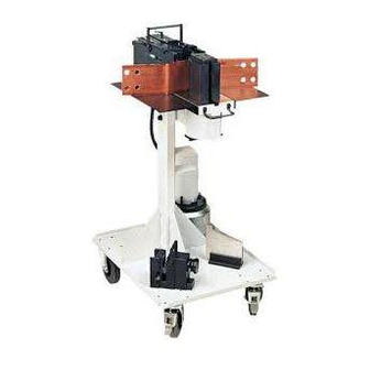
Max. Dimensions: SLB 125 with carriage: Table height: Total height: 1145 Width: Depth: SLB 125 with table stand Total height: 415 mm Width: 500 mm Depth: 677 mm 3. Operative range The following types of busbars can be cut, perforated and bent using the SLB125: up to a max. -
Page 8: Commissioning
4. Commissioning Snap coupling Coupling Hold the coupling body (KM) against the sliding sleeve (SH) and push onto the coupling plug (KS). Uncoupling Hold the coupling body (KM) against the sliding sleeve (SH) and pull from the coupling plug (KS). •... -
Page 9: Stroke Limiter (Required For Bending)
5. Stroke Limiter (required for bending) For bending, the bending angle can be adjusted using the stroke limiter. A larger stroke is required for cutting and perforating than for bending. To ensure that the adjusted bending angle is retained, the stroke limiter can be switched On and Off for cutting and perforating using an indexing bolt. -
Page 10: Cutting
6. Cutting Installing the blade • Press the lock (1) and hold. • Insert the blade (2) in guide (A). • Release the lock (1) and pull back to the starting position if necessary. Information! The lock (1) must be in the starting position; otherwise, the hydraulic unit cannot be switched on. -
Page 11: Perforating
7. Perforating Instructions for using the tools • The hole diameter must not be smaller than the thickness of the material. Failure to observe this rule will result in damage to the tool. • It is impermissible to enlarge holes using the progressive die technique. Similarly, the minimum distance between two holes or between a hole and the edge of the busbar must be at least the thickness of the tool. -
Page 12: Installing The Perforating Tool
Profile tools Upper tools have a straight pin on the outer diameter. To align the upper tool, there are 2 grooves in the upper tool holder. Lower tools have two V grooves on the outer diameter arranged at 90° to one another. When fitting, each V groove (depending on the required perforation or the alignment of the upper tool) must be aligned with the grub screw (9). -
Page 13: Perforating Without The Hole Template
Perforating without the hole template CAUTION! Damage to upper tool when perforating aluminium When perforating aluminium, the upper tool may become caught in the workpiece. The workpiece is not wiped off. Therefore: – To prevent this from happening, the upper tool should be greased or oiled. •... -
Page 14: Perforating With The Hole Template For Din Perforations
Perforating with the hole template for DIN perforations The hole patterns of the hole templates comply with DIN 43673. The busbar widths and hole patterns for each template can be taken from the following table. Ord. no. b (mm) Hole pattern b (mm) Hole pattern e1 (mm) e2 (mm) e3 (mm) -
Page 15: Bending
8. Bending Installing the bending device • Insert the bending device (7) into the guide (B). Bending The bending angle is adjusted using the stroke limiter (25). The millimetre scale indicates the amount of forward stroke. The correct settings for the required bending angle should be determined by means of test bends (see table). - Page 16 Copper busbars 120x10 Aluminium busbars 120x10 Bending Angles Stroke in mm Bending Angles Stroke in mm 15° approx. 24 15° approx. 23.5 30° approx. 28.5 30° approx. 27.2 45° approx. 33.5 45° approx. 32 60° approx. 38.5 60° approx. 36.5 75°...
-
Page 17: Perforating Tools For Laminated Copper And Flat Bars Less Than 34 Mm Wide
9. Perforating tools for laminated copper and flat bars less than 34 mm wide Operative range Perforating tools with extra wipers must be used for laminated copper and flat bars less than 34 mm wide. Maximum busbar thickness (non-insulated): up to 10 mm Each upper tool has a separate extra wiper. -
Page 18: Assembly
Assembly Mount the extra wiper (17) on the holder (20) and press down firmly by hand (caution with the centring point!). Disassembly Pull the extra wiper (17) from the holder (20). -
Page 19: Adjustable Template, Order No.: 31890, For Perforating Tool
10. Adjustable template, order no.: 31890, for perforating tool Adjusting the hole template The scale on the x axis (25) indicates the distance (X) between the template stop and the centre of the hole to be punched. The scales on the y axis (26) indicate the distance (Y) between the supporting surface of the busbar on the template and the centre of the hole to be punched. -
Page 20: Inserting The Hole Template
Inserting the hole template • In order to perforate, the indexing bolt (3) must be locked into the V groove. If this is not the case, pull up the indexing bolt (3), rotate through 90° and lock into the V groove (see page 3). Note! The hole templates must be inserted as shown. -
Page 21: Swan-Neck Bending Tools
11. Swan-neck Bending Tools Operative range Copper and aluminium busbars can be bent using the swan-neck bending tools. The maximum cross-section is as follows: for swan-neck bending tool (small), order no.: 31425 for aluminium: 120 x 10 for copper: 120 x 6 80 x 10 for swan-neck bending tool (large), order no.: 31646 for aluminium:... -
Page 22: Tables For Swan-Neck Bending Tools
Tables for swan-neck bending tools Swan-neck bending tool (small), order no.: 31425 Shank length F (at Hmax) = Insertion size X minus 15mm Min. length for insertion L min = 22 mm Bending radius = 7.5 mm Width of swan-neck = 20 mm Material Width x... -
Page 23: Swan-Neck Bending Tool (Small), Order No.: 31646
Swan-neck bending tool (small), order no.: 31646 Shank length F (at Hmax) = Insertion size X minus 25mm Min. length for insertion L min = 42 mm Bending radius = 10 mm Width of swan-neck = 40 mm Material Width x Max. -
Page 24: Additional Bending Tool For Small Lug Lengths, Order No.: 31636
12. Additional Bending Tool for Small Lug Lengths, Order No.: 31636 Operative range Using the standard bending tool, order no.: 31243, and the additional bending tool, order no.: 31636, small lug lengths up to 25 mm (0.984“) can be bent. The maximum cross-section is as follows: for aluminium: 120 x 10 for copper... -
Page 25: Installing The Bending Tool
Installing the bending tool • Insert the bending tool (7) in the guide (B). Bending See chapter 8 “Bending”... -
Page 26: Mm U Bending Tool, Order No. 42430
13. 60mm U bending tool, order no. 42430 Range of application Using the 60mm U bending tool, order no. 42430, small U shapes from 60 mm onwards can be bent inwards. Installing the U bending tool • Remove the indexing bolt. •... - Page 27 • Remove mandrel (13). • Insert the new bending mandrel. • Pull up the indexing bolt. • Rotate the indexing bolt through 90°. • Allow the indexing bolt to lock into the V groove. • Screw in 2 cylinder screws (40). •...
-
Page 28: Bending
Bending See chapter 8 “Bending” Removing the U bending tool Disassembly in reverse assembly order. CAUTION! Damage to the SLB if mandrel (13) is not fixed with screws (40). The mandrel (13) may turn during cutting or perforating if it is not fixed with the screws (40). -
Page 29: Lamella Cutter, Order No.: 45445
14. Lamella cutter, order no.: 45445 Range of application The lamella cutter is suitable for cutting: Lamellar copper busbars with a maximum size for insertion of 129 mm x 18 mm. Installing the lamella cutter • Press lock (1) and hold it. •... -
Page 30: Cutting
Cutting CAUTION! Damage to device and risk of injury from swarf and cutting debris Unremoved swarf and cutting debris may cause the blade to tilt and break. Therefore: – Keep the lamella cutter free of swarf and cutting debris. • In order to cut, the indexing bolt (3) must be locked into the V groove. If this is not the case, pull up the indexing bolt (3), rotate through 90°... -
Page 31: Maintenance
After each use: Clean guides A and B to remove dirt, swarf etc. Clean blade guide M to remove swarf and cutting debris. Every week: Clean SLB 125. Perforating tool After 20 perforations: Grease or oil the upper tool Before each tool installation: Clean the mounting hole for the lower tool. - Page 32 Repairs / Service Wettiner Str.24 06193 Wettin-Löbejün www.uwe-hartig.de info@uwe-hartig.de Germany...
Need help?
Do you have a question about the SLB 125 and is the answer not in the manual?
Questions and answers