Table of Contents
Advertisement
Quick Links
Advertisement
Table of Contents

Related Manuals for NovoPress SLB 125


Summary of Contents for NovoPress SLB 125
-
Page 1: Repair Instructions
Repair Instructions SLB 125 40070\r01eng 0616... -
Page 2: Table Of Contents
Contents Page Safety regulations General information Changing the limit switch ....................1 Replacing the cylinder ....................... 2 SPARE PARTS-parts lists / drawings 40070 SLB125 basic unit with carriage ..................6 31242 Cutting tool........................11 31890 Adjustable hole template ....................14 31243 R 10 bending tool...................... - Page 3 Leave safety devices where they belong. Hand tools may not be installed as fixtures. Repair and maintenance. Have repairs and maintenance work carried out in an authorised NOVOPRESS specialist workshop. Only use original and identical NOVOPRESS spare parts. We reject all responsibility and liability for work carried out by third- party personnel.
- Page 4 SAFETY INSTRUCTIONS FOR HYDRAULIC EQUIPMENT Please read the operating instructions. Acquaint yourself with the hydraulic equipment. Provide the equipment with the necessary care. Always keep the equipment in operational condition. Cleanness is an essential requirement for good and safe working. Switch off the electric power supply to the hydraulic equipment, •...
-
Page 5: Changing The Limit Switch
WARNING! Before beginning any maintenance or repair work, disconnect the hydraulic unit. Changing the limit switch 1.1. Unscrew indexing bolt (62) and remove it together with spacer bush (61). 1.2. Unscrew bolts (25). 1.3. Remove cover (9). 1.4. Unscrew bolts (48). 1.5. -
Page 6: Replacing The Cylinder
Replacing the cylinder Disassembly 2.1. Unscrew indexing bolt (62) and remove it together with spacer bush (61). 2.2. Unscrew bolts (25). 2.3. Remove cover (9). 2.4. Remove stroke adjustment plate (60). 2.5. Unscrew bolts (48). 2.6. Remove limit switch (15) and place it on the workplate. -
Page 7: Unscrew
2.11. Unscrew bolts (68). Note Do not adjust the nuts. 2.12. Unscrew bolt (22). 2.13. Remove the unit comprising spindle bearing block (13), spindle (14), spindle guide (12) and switch valve (10) in such a way as to ensure that the spindle does not become bent. - Page 8 2.20. Unscrew loose nuts (M) step by step from the assembly bolts on alternating sides until the return spring is not tensioned. 2.21. Unscrew assembly bolts (32245). 2.22. Remove cylinder (2), piston (3) and return spring (29). 2.23. Wearing parts - replace O-ring (33), bearing ring (32) and scraper (34) if required.
- Page 9 Assembly 2.1. Place bearing ring (32) and O-ring (33) on piston (3). 2.2. Insert piston (3) in cylinder (2). 2.3. Push return spring (29) onto the piston rod. 2.4. Insert scraper (34) into plate (1). 2.5. Insert cylinder (2) with the components assembled into plate (1).
-
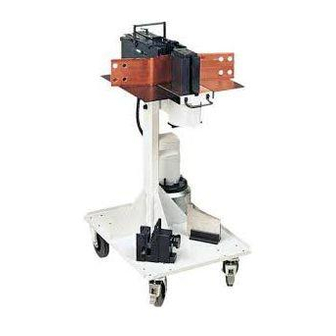
Page 10: 40070 Slb125 Basic Unit With Carriage
40070 SLB125 basic unit with carriage Item Description Ord. no. Qty. SLB 125 basic unit 40200 SLB 125 carriage assy. 40390... - Page 11 40200 SLB 125 basic unit Item Country Description Ord. no. Qty. code Table 30769 Cylinder 39696 Piston 31029 Pressure piece 39697 Tool retainer 31032 Cutting bar 31033 Pressure plate 31034 Anti-twist device 31035 Cover 39624 Switch valve 39625 Switching block...
-
Page 12: Spacer
Item Country Description Ord. no. Qty. code Washer 11203 Countersunk screw M4x10 11070 Novopress plate 33316 Cheese-head screw M3x8 12377 Base 40339 Cheese-head screw M10x12 11686 Straight pipe connector 13376 Adjustable angled coupling 13414 Union nut 1725 Stroke adjustment plate... - Page 13 40200 SLB125 basic unit...
-
Page 15: 31242 Cutting Tool
31242 Cutting tool Item Description Ord. no. Qty. Blade 31039 Blade bracket 31041 Sleeve 31307 Guard plate 31049 Cheese-head screw M5x50 12143 Knurled screw M8x25 14138 Hexagonal nut M8 11367 Protective glass 31323 Cheese-head screw M8x20 11094 Cheese-head screw M5x10 12350 Sleeve 31593... - Page 16 30980 Hole puncher Item Description Order no. Qty. Body 30971 Piston 30973 Scraper 30974 Retractor washer 30975 Bracket, right 30972 Bracket, left 31122 Spacer block 30977 Cover disc 30978 Handle piece 31289 Handle 31291 Spring system, yellow 13926 Straight pin 10m6x30 14072 Straight pin 6m6x12 13150...
- Page 17 30980 Hole puncher...
-
Page 18: 31890 Adjustable Hole Template
31890 Adjustable hole template Item Description Order no. Qty. Guide rail 31891 Slide 31892 Guide plate 31893 Adjusting plate 31894 Scale 31071 Knurled screw 14260 Pressure spring 14261 Clamping lever 14262 Countersunk screw 11197 Adjusting plate 31912 Scale 31965 Scoring plate 31981... -
Page 19: 31243 R 10 Bending Tool
31243 R 10 bending tool Item Description Ord. no. Qty. Bending mandrel 31038 Handle shaft 14197 Protective disc 31619 31732 R 6 bending tool Item Description Ord. no. Qty. R6 bending mandrel 31747 Handle shaft 14197 Protective disc 31619... -
Page 20: 31425 Step Bending Tool, Small
31425 Step bending tool, small Item Description Ord. no. Qty. Step bending pressure piece 1 31423 Step bending pressure piece 2 31424 Step bending radius 31327 Stop bridge 31774 Retractor 40326 Guide bars 31339 Cheese-head screw M5x10 11081 Cheese-head screw M5x20 11010 Cheese-head screw M8x30 12590... -
Page 21: 31646 Step Bending Tool, Large
31646 Step bending tool, large Item Description Ord. no. Qty. Step bending pressure piece 1 31338 Step bending pressure piece 2 31647 Step bending radius 2643 Stop bridge 31774 Retractor 40326 Guide bar 31339 Cheese-head screw M5x10 11081 Cheese-head screw M6x12 11259 Cheese-head screw M8x30 12590... - Page 22 31636 Hinge bending tool Item Description Ord. no. Qty. Spacer plate 31913 Hinge half 31914 Spring retainer 31915 Bolt 31916 Spiral spring 14210 Countersunk screw M5x10 11197 Countersunk screw M5x16 12755 Circlip 11644 Threaded rod 31653 Ball head 11243 Stop 31641...
- Page 24 Repairs / service Wettiner Str.24 06193 Wettin-Löbejün www.uwe-hartig.de info@uwe-hartig.de Germany...
Need help?
Do you have a question about the SLB 125 and is the answer not in the manual?
Questions and answers