Advertisement
Quick Links
Advertisement

Related Manuals for Bosch D132A


Summary of Contents for Bosch D132A
- Page 1 Smoke Detector Reversing Relay Module D132A D132A Installation manual...
- Page 3 Install, test and maintain the module according to these instructions, NFPA 72, local codes, and the authority having jurisdiction (AHJ). Failure to follow these instructions can result in failure of a detector to initiate an alarm event. Bosch Security Systems, Inc. is not responsible for improperly installed, tested or maintained devices.
- Page 4 To restore the smoke detectors to normal, reset the smoke detectors. The following table lists control panels compatible with the D132A: Control panels...
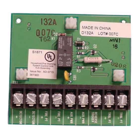
- Page 5 Smoke Detector Reversing Relay Module Description | en Figure 2.1: D132A smoke detector reversing relay module 1 Mounting holes 6 Positive (+) power for module 2 Positive (+) to detector 7 Negative (-) power for module 3 Negative (-) to detector...
-
Page 6: Installation
Align the module with an available three-hole module mounting location in the enclosure. Fasten the module to the enclosure with the three supplied screws. For mounting locations inside the enclosure, see the control panel’s Installation Instructions. 2019.08 | 05 | F.01U.069.463 Installation manual Bosch Securiity Systems, B.V. - Page 7 The interconnecting wires between the control panel and external power supply must be in conduit. The power source for both the auxiliary power supply and the control panel must be from the same dedicated AC branch circuit. Bosch Securiity Systems, B.V. Installation manual 2019.08 | 05 | F.01U.069.463...
- Page 8 Wiring to a B Series panel 4.1.1 Two-wire wiring for 12 VDC supplied by the control panel Figure 4.1: Two-wire wiring of D132A modules to a B Series control panel for power supplied by the panel 1 Detector loop (2‑wire) 9 Connection from D125B switch power to control panel’s A output relay (NC).
- Page 9 Wiring | en Notice! The illustration shows the D132A modules wired for both detector loops triggered by the same output. For loops triggered by separate outputs, connect one D132A module reverse trigger to B output and the other D132A revese trigger to C output.
- Page 10 4.1.2 Four-wire wiring for 12 VDC supplied by the control panel Figure 4.2: Four-wire wiring of D132A modules to a B Series control panel for 12 V power supplied by the panel 1 D132A module 9 D132A Trigger connection to panel’s...
- Page 11 4.1.3 Two-wire wiring for 12 VDC supplied by an external power supply Figure 4.3: Two-wire wiring D132A modules to a B Series panel for 12 V power supplied by an external power supply 1 Detector loop (2‑wire) 9 Connection from D125B switch power to control panel’s A output relay (NC).
- Page 12 4.1.4 Four-wire wiring for 12 VDC supplied by an exernal power supply Figure 4.4: Four-wire wiring D132A modules to a B Series panel for 12 V power supplied by an external power supply 1 External power supply (12 VDC) 9 Negative (-) fire point and AUX PWR connection to panel’s COM terminal...
- Page 13 Wiring to a D6412 or D4412 panel 4.2.1 Two-wire wiring for 12 VDC supplied by the control panel Figure 4.5: Two-wire wiring D132A modules to a D6412 or D4412 control panel for 12 VDC supplied by the panel 1 Detector loop (2‑wire) 6 Trigger to reverse power...
- Page 14 4.2.2 Two-wire wiring for 12 VDC supplied by an external power supply Figure 4.6: Two-wire wiring a D132A module to a D6412 or D4412 control panel for 12 VDC supplied by an external power supply 1 Detector loop (2‑wire) 7 Connections for trouble point...
- Page 15 PHONE LINE SEIZED RING TELCO CORD MODEL D161 Figure 4.7: Two-wire wiring of D132A modules to a G Series control panel for power supplied by the panel 1 Detector loop (2‑wire) 9 Connection from D125B switch power to control panel’s C relay (switched Aux).
- Page 16 Common (-) +24 VDC +12 VDC Figure 4.8: Four-wire wiring of D132A modules to a G Series control panel for 12 V power supplied by the panel 1 D132A module 9 Connection from reverse trigger on D132A modules to control panel A or B relay Pulls High in Alarm.
- Page 17 7 Positive (+) fire point and AUX PWR 15 Last smoke detector on the detector connection to panel’s AUX power loop terminal 8 Negative (-) fire point and AUX PWR connection to panel’s COMMON terminal Bosch Securiity Systems, B.V. Installation manual 2019.08 | 05 | F.01U.069.463...
- Page 18 RING TELCO CORD MODEL D161 Figure 4.9: Two-wire wiring D132A modules to a G Series panel for 12 V power supplied by an external power supply 1 Detector loop (2‑wire) 9 Connection from D125B switch power to control panel’s C relay (switched...
- Page 19 MODEL D161 Common (-) +24 VDC +12 VDC Figure 4.10: Four-wire wiring of D132A modules to a G Series control panel for 12 V power supplied by an external power supply Bosch Securiity Systems, B.V. Installation manual 2019.08 | 05 | F.01U.069.463...
- Page 20 COM terminal 2 D132A module 10 Connection from reverse trigger on D132A modules to control panel A or B relay Pulls High in Alarm. Use a D130/ PAM-4 to accomplish this.. 3 Resistor R4: for 4‑wire use, cut the...
- Page 21 On a G Series control panel, A Relay (D130/PAM-4) will need to be connected to the on-board A or B output and will be used to activate the module's reverse trigger. Bosch Securiity Systems, B.V. Installation manual 2019.08 | 05 | F.01U.069.463...
-
Page 22: Specifications
10.2 VDC to 13.9 VDC Environmental Relative Humidity 5% to 93% at +86°F (+30°C) Temperature (operating) +32°F to +120°F (0°C to +49°C) Mechanical Dimensions (HxW) 3 in. x 3 in. (7.6 cm x 7.6 cm) 2019.08 | 05 | F.01U.069.463 Installation manual Bosch Securiity Systems, B.V. - Page 23 Bosch D263THS D263 ● * D132A does not operate at 24 V; use only on 12 V powered loops. Compatible 4 wire detectors Underwriters Laboratories (UL) has found the following 4‑wire detectors to be compatible with the D132A: Manufacturer...
- Page 24 | Compatible detectors Smoke Detector Reversing Relay Module 2019.08 | 05 | F.01U.069.463 Installation manual Bosch Securiity Systems, B.V.
- Page 26 Bosch Security Systems, Inc. Bosch Sicherheitssysteme GmbH 130 Perinton Parkway Robert-Bosch-Ring 5 Fairport, NY 14450 85630 Grasbrunn Germany www.boschsecurity.com © Bosch Security Systems, Inc., 2019...
Need help?
Do you have a question about the D132A and is the answer not in the manual?
Questions and answers