Table of Contents
Advertisement
Quick Links
Advertisement
Table of Contents

Related Manuals for Bosch D8128D


Summary of Contents for Bosch D8128D
- Page 1 D8128D OctoPOPIT Module Installation Guide...
-
Page 2: Table Of Contents
Figure 1: D8128D OctoPOPIT Layout ........................6 Figure 2: Mounting Enclosure ..........................7 Figure 3: Wiring the D8128D to a Control Panel Wired to a D8125 POPEX Module ..........9 Figure 4: Wiring Multiple D8128D Modules Using Molex Connectors ..............10 Figure 5: D8128D Sensor Loops ........................... 10 Tables Table 1: Document Organization ..........................3... -
Page 3: Introduction
The D8128D OctoPOPIT Module combines the functions of the D8125 POPEX Module and the D8127/D9127 POPIT Modules to provide eight off-board points (Class B [Style B]) in a single module. You can wire both the D8128D OctoPOPIT and D8125 POPEX in parallel to the ZONEX Bus Terminals on the same control panel. Document Organization Table 1 identifies the sections of this document. -
Page 4: Overview
Approximately 1 sec. OctoPOPIT sensor loops are supervised with a 1 kΩ EOL resistor, D105BL or D105FL, for fire supervisory applications. Cabling Burglary D8128D OctoPOPITs can be installed up to 200 ft (61 m) 4 Ω maximum from Applications: the control panel using standard 4-conductor 22 AWG (0.8 mm) wire. Fire Applications: Use UL Listed fire rated cable approved by the AHJ when connecting fire- initiating or fire-supervisory devices to the D8128D. -
Page 5: Compatible Control Panels And Maximum Number Of D8128 Connections
OctoPOPITs and other powered devices you want to connect to your system. Use the D8128D with the control panels shown in Table 3 below. The maximum number of D8128D Modules that can be connected to your system depends on the control panel being used. Refer to Table 6 on page 11 for proper switch settings. -
Page 6: Installation
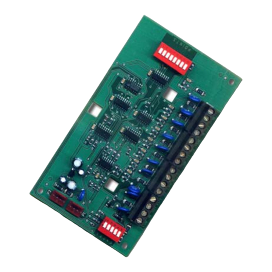
Figure 1: D8128D OctoPOPIT Layout 3.1.1.2 Line Termination Switch Settings Switch 5 sets line termination. • If no D8125 POPEX is connected to ZONEX 1, set switch 5 of only one D8128D connected to those terminals to the ON position. D8128D Installation Guide F01U070537-07 Page 6 ©... -
Page 7: Point Dip Switches
Point DIP Switches Each point connected to the D8128D is enabled or disabled by turning its respective DIP switch to the closed or open position, respectively. For example, to disable a device connected to Terminal P3 (Point 3), move DIP Switch 3 to the OPEN position. -
Page 8: Wiring
AC conduit/wiring or electrical devices that emit fields of electromagnetic interference (EMI). 3.3.1 Connect the D8128D to the Control Panel using the Terminal Strip When connecting the D8128D to the control panel using the D8128D terminal strip, make the following connections. D8128D... -
Page 9: Figure 3: Wiring The D8128D To A Control Panel Wired To A D8125 Popex Module
D8128D Figure 3 shows how to wire a D8128D to the control panel wired to a D8125 POPEX module. ZONEX BUS 1 ZONEX BUS 1 Switch 1 CLOSED Switch 1 OPEN (Ponts 9 through 72) (Ponts 73 through 127) Supervised Bus 1 Bus 1 cont’d... -
Page 10: Wiring Multiple D8128D Modules To The Control Panel Using Molex Connectors
When connecting multiple D8128D Modules to a control panel, connect the control panel terminals to P1 or the Com, In, Out, and +12 V Terminals on the first D8128D. Then connect P2 of the first D8128D to P1 of the second D8128D and so on. -
Page 11: Switch Settings For Control Panels
113 to 120 233 to 240 121 to 127 241 to 247 Table 6: D8128D Address Switch Settings After any programming or hardware change, do a functional test of the system as required by local codes. D8128D Installation Guide F01U070537-07 Page 11 ©... - Page 12 Bosch Security Systems, Inc. 130 Perinton Parkway Fairport, NY 14450-9199 www.boschsecurity.com © 2015 Bosch Security Systems, Inc. F01U070537-07...
Need help?
Do you have a question about the D8128D and is the answer not in the manual?
Questions and answers