Advertisement
Quick Links
Advertisement

Related Manuals for Bosch D113


Summary of Contents for Bosch D113
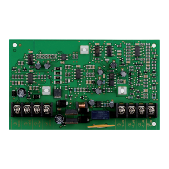
- Page 1 Battery Lead Supervision Module D113 Installation manual...
- Page 3 Install, test and maintain the module according to these instructions, NFPA codes, local codes, and the authority having jurisdiction (AHJ). Failure to follow these instructions can result in failure of a detector to initiate an alarm event. Bosch Security Systems, Inc. is not responsible for improperly installed, tested or maintained devices.
- Page 4 This module provides supervision of the battery lead connection between the module and one or two batteries in a system controlled by a Bosch 12 VDC FACP or control/communicator. This module may be used with other panels when referenced in the panel’s installation/ operation instructions.
- Page 5 The module will also indicate a trouble condition if one or both of the batteries are connected with their polarity reversed. To reset, disconnect the batteries and reconnect properly. Bosch Security Systems, Inc. Installation manual 2020.03 | 10 | F.01U.036.374...
-
Page 6: Installation
Connect the ORANGE wire lead provided with the module to the auxiliary power positive terminal on the FACP or the auxiliary power supply. Connect the other end of the ORANGE wire to Terminal 3 (VAUX+) on the module. 2020.03 | 10 | F.01U.036.374 Installation manual Bosch Security Systems, Inc. - Page 7 If the module is supervising a single battery, connect the battery leads to Terminals 5 and 6 and connect the jumper wires to Terminals 7 and 8, as shown in the following Figure. Bosch Security Systems, Inc. Installation manual 2020.03 | 10 | F.01U.036.374...
- Page 8 Figure 4.2: Jumper locations for single‑battery installations Restoring power to the FACP Close the 120 VAC dedicated breaker that controls the power input to the FACP and reconnect the standby batteries. 2020.03 | 10 | F.01U.036.374 Installation manual Bosch Security Systems, Inc.
-
Page 9: Specifications
Specifications | en Specifications Electrical Voltage (input range) 10.2 V min to 13.9 V max Voltage (battery) 12 V nominal Current draw 45 mA For battery calc, use 45 mA for alarm and 45 mA for standby Bosch Security Systems, Inc. Installation manual 2020.03 | 10 | F.01U.036.374... - Page 10 | Specifications Battery Lead Supervision Module 2020.03 | 10 | F.01U.036.374 Installation manual Bosch Security Systems, Inc.
- Page 12 F. 0 1U. 0 36. 3 74 Bosch Security Systems, Inc. Bosch Sicherheitssysteme GmbH 130 Perinton Parkway Robert-Bosch-Ring 5 Fairport, NY 14450 85630 Grasbrunn Germany www.boschsecurity.com © Bosch Security Systems, Inc., 2020...
Need help?
Do you have a question about the D113 and is the answer not in the manual?
Questions and answers