Table of Contents
Advertisement
Advertisement
Table of Contents

Subscribe to Our Youtube Channel
Related Manuals for Bosch D8125


Summary of Contents for Bosch D8125
- Page 1 D8125 Installation and Operation Guide POPEX Module...
-
Page 2: Table Of Contents
FCC Notice ................................4 Introduction .............................. 5 Specifications .............................. 5 9000 and G Series Point Expansion Overview ................... 6 D8125 POPEX and D9127U/T POPIT Modules ....................7 2.1.1 Listings ................................ 7 Non-G 9000 Series Point Expansion ......................7 D8112G1/D8112G2 Point Expansion ......................8 3.2.1... -
Page 3: Ul Applications
* A model “U” POPIT mounted within a tampered enclosure can be used in place of a model “T” POPIT. The following describes the classification of the Bosch Security Systems modules. Please reference the NFPA 72 for the specific details of IDC, SLC, NAC conditions. -
Page 4: Fcc Notice
D8125 | Installation and Operation Guide | FCC Notice FCC Notice This equipment generates low level radio frequency energy. If not installed in accordance with the manufacturer’s instructions, it may cause interference to radio and television reception. It has been type tested and found to comply with the specifications in Subpart J of Part 15 of FCC rules for Class B Computing Devices. -
Page 5: Introduction
D8125 | Installation and Operation Guide | 1.0 Introduction 1.0 Introduction This guide covers installation of the D8125 POPEX Module for use with the D9127U/T POPITs on the new G Series control panels (B9512G, B9512G-E, B8512G, B8512G-E), G Series control panels (D9412GV4, D7412GV4, D7212GV4, D9412GV3, D7412GV3, D7212GV3, D9412GV2, D7412GV2, D7212GV2, D9412G, D7412G, D7212G), and D9124 control panel. -
Page 6: 9000 And G Series Point Expansion Overview
9000 and G Series Point Expansion Overview 2.0 9000 and G Series Point Expansion Overview The POPITs are connected to each other and the D8125 through a supervised data loop. POPEX modules connect to ZONEX terminals (OUT, IN, POWER+, COMMON) on the control panel. -
Page 7: D8125 Popex And D9127U/T Popit Modules
Master Armed, a Missing Alarm event is generated. D8125 POPEX and D9127U/T POPIT Modules D9127U/T POPITs use the D8125 POPEX Module to report to the control panel. Each D8125 supports up to 119 POPIT points. The B9512G, D9412GV4, D9412GV3, D9412GV2, and D9412G support two D8125 POPEX Modules. -
Page 8: D8112G1/D8112G2 Point Expansion
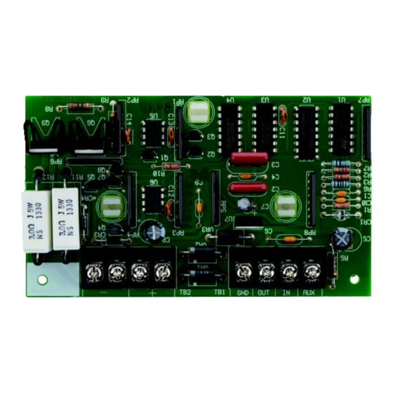
The D8125 POPEX Module is a hardware accessories for the Bosch Security Systems Zone Expansion (ZONEX) system. The D8125 POPEX Module is a Point Of Protection EXpander. One or two POPEX Modules can be used to interface zone expansion loops to the D8112G series. Each POPEX Module can monitor up to 63 POPIT Modules, and as many as 126 individual POPIT Modules can be monitored in a ZONEX system with two POPEX Modules. -
Page 9: D9124 Point Expansion
Section 2.0 9000 and G Series Point Expansion for details regarding POPIT installation. You can connect up to four data expansion loops to one D8125 input at the motherboard. Data Loops 1 to 4 connect to the D8125 POPEX 1 input on the motherboard (Terminals 11 through 18). Data Loops 5 to 8 connect to the D8125 POPEX 2 input at the motherboard (Terminals 19 through 26). -
Page 10: Installation
Follow the procedure below to install the D8125 in the enclosure with the control panel or B600. 1. Align the D8125 POPEX module with any of the four mounting locations in the enclosure. See Figure 2. 2. Use the screws provided with the module to secure it in the enclosure. -
Page 11: 9000 Series And G Series
4. Connect the AUX terminal of the D8125 to ZONEX POWER + terminal. Do not connect more than one D8125 to ZONEX 1 (IN and OUT terminals) or ZONEX 2 (IN and OUT terminals). Bosch Security Systems B.V. | 2020.04 | F01U036298-15... -
Page 12: Wiring Popits To The Data Expansion Loop
D8125 | Installation and Operation Guide | 4.0 Installation 4.2.4 Wiring POPITs to the Data Expansion Loop Use one 2-wire data expansion loop or distribute the POPITs on up to three loops. Setting DIP switches on the POPIT modules assigns them to point numbers. Refer to Section 4.2.6 POPIT Module Point Assignments. -
Page 13: Wiring Data Expansion Loops To Popex Modules
There are two positive (+) and two negative (-) data expansion loop terminals on each POPEX module. Follow the procedure below to connect the data expansion loops to the D8125 POPEX Module (refer to Figure 3). Remember you can only connect a maximum of 119 POPITs to one D8125. - Page 14 D8125 | Installation and Operation Guide | 4.0 Installation Figure 3: Connecting the D8125 POPEX to the control panel Bosch Security Systems B.V. | 2020.04 |F01U036298-15...
-
Page 15: Popit Module Point Assignments
4.2.7.1 POPIT Labels Two sheets of peel-off POPIT labels are supplied with the D8125 POPEX module. Use the sheet marked Bank1 for Points 9 to 127. Use the sheet marked Bank2 or Points 129 to 247. Each label has two parts. Place the smaller part, with just the point number on it, on the chip. Place the larger part with the switch settings on the base of the POPIT. -
Page 16: Popit Module Installation
The zone expansion loop is a two-conductor wire interconnecting all POPIT Modules assigned to a single POPEX (see Figure 4). Up to three zone expansion loops can be connected to one D8125 when using unshielded cable. The required wire gauge for the zone expansion loop(s) (up to three max.) can be determined using Table 4. - Page 17 D8125 | Installation and Operation Guide | 4.0 Installation Remember: Up to 63 POPIT modules can be connected to one POPEX module. Connect the positive (+) Data terminal from one POPIT to the positive (+) Data terminal on the next POPIT.
- Page 18 D8125 | Installation and Operation Guide | 4.0 Installation Figure 4: D8112G1/G2 POPEX and POPIT Module Installation Bosch Security Systems B.V. | 2020.04 |F01U036298-15...
-
Page 19: Popit Module Assignments
D8125 | Installation and Operation Guide | 4.0 Installation 4.3.3.2 Wiring POPITs to a POPEX Module Two positive (+) and two negative (-) zone expansion loop terminals are provided on each POPEX Module for wiring convenience. When using two POPEX Modules, each module must have its own expansion loop (e.g., POPIT Modules assigned to POPEX... -
Page 20: Popit Labels
D8125 | Installation and Operation Guide | 4.0 Installation 4.3.5 POPIT Labels Four sets of POPIT I.D. labels are provided with each POPEX Module. Each set is associated with either POPEX #1 (PX 1) or POPEX #2 (PX 2), and with either the horizontal or vertical mode. In every POPEX/POPIT installation, at least two sets of these labels are NOT used. - Page 21 D8125 | Installation and Operation Guide | 4.0 Installation ZN101S2 Memory of Previous Events: The D1252A displays a memory code to annunciate events which have taken place since the system was last armed. = Alarm Memory = Trouble Memory = Alarm and Trouble Memory...
- Page 22 D8125 | Installation and Operation Guide | 4.0 Installation 4.3.5.1 POPEX/POPIT Configurations Two configurations, horizontal (Table 5) and vertical (Table 6) are used to organize points of protection. Both modes provide the ZONEX system with the maximum of 126 points of protection. The two Zone Expansion terminals are typically used to group POPITs in a ZONEX system.
- Page 23 D8125 | Installation and Operation Guide | 4.0 Installation Table 5 and Table 6 display all POPIT assignment switch settings for both the horizontal and vertical modes (e.g., 1 2 3 4 - -). Numbers 1 through 6 indicate switches 1-6 on the POPIT Module. The dash (-) indicates a switch is in the OFF or open position.
- Page 24 D8125 | Installation and Operation Guide | 4.0 Installation HORIZONTAL MODE – POPEX AND POPIT MODULES D8112 D8112 D8112 D8112 D8112 D8112 D8112 D8112 MASTER MASTER MASTER MASTER MASTER MASTER MASTER MASTER ZONE 1 ZONE 2 ZONE 3 ZONE 4...
- Page 25 D8125 | Installation and Operation Guide | 4.0 Installation VERTICAL MODE – POPEX AND POPIT MODULES POPEX 1 (D8112G1/G2 TERMINAL 28) POPEX 2 (D8112G1/G2 TERMINAL 27) D8112 D8112 D8112 D8112 D8112 D8112 D8112 D8112 MASTER MASTER MASTER MASTER MASTER MASTER...
-
Page 26: Popit Displays
D8125 | Installation and Operation Guide | 4.0 Installation 4.3.6 POPIT Displays The status of each POPIT Module is transmitted to the D8112G1/G2 control panel. The status is recorded and held in the D8112G1/G2 memory buffer until the system is armed and the exit delay time has expired. -
Page 27: Central Station Reports
D8125 | Installation and Operation Guide | 4.0 Installation 4.3.7. Central Station Reports 4.3.7.1 Pulse and BFSK Reporting When a POPIT initiates an alarm or trouble report, the D8112G/G2 transmits the reports indicating the D8112 master zone tripped. Two POPIT reports to the central station (in addition to alarm, trouble, and restoral reports for each master zone) are supported. -
Page 28: Local Status Test
D8125 | Installation and Operation Guide | 4.0 Installation 4.3.8 Local Status Test 4.3.8.1 Operation While disarmed, the security system status can be checked by entering [COMMAND 44] at the D1252A Keypad. This command also initiates a system walk test (described in the D1252A Security System User’s Guide, P/N: 71-04415-000) as part of the status test. - Page 29 D8125 | Installation and Operation Guide | 4.0 Installation Figure 8 illustrates a system with six POPITs assigned in programming to each of five master zones, and seven POPITs installed for master zone 5. An “extra” POPIT condition will be displayed when [COMMAND 44] is entered at the D1252A.
- Page 30 D8125 | Installation and Operation Guide | 4.0 Installation If an extra POPIT is installed the system will indicate that it is READY TO ARM. The “extra” POPIT message will only be displayed when [COMMAND 44] is entered at the D1252A (see Figure 11). Non-normal conditions in all POPITs assigned to the master zone with the extra POPIT may not be correctly reported as opens or shorts to the D8112G.
-
Page 31: Troubleshooting
D8125 | Installation and Operation Guide | 5.0 Troubleshooting 5.0 Troubleshooting 9000 Series and G Series 5.1.1 Service Walk Test Shows Extra Points The Service Walk Test differs from the standard Walk Test in that POPITs whose switches are set for a point number not programmed in the control panel appear in the test. - Page 32 D8125 | Installation and Operation Guide | 5.0 Troubleshooting SERVICE WALK ? 246 PTS TO TEST Test a device POINT TEXT (Text displays 60 seconds) 245 PTS TO TEST Test a device POINT TEXT (Text displays 60 seconds) 244 PTS TO TEST...
-
Page 33: Problems With Points
D8125 | Installation and Operation Guide | 5.0 Troubleshooting 5.1.2 Problems with Points If you incorrectly set the switches on a POPIT you may create both a missing and extra point. When you find a missing point, perform a Service Walk Test to search for extra points. - Page 34 D8125 | Installation and Operation Guide | 5.0 Troubleshooting System Diagnosis Remedy Sensor Reset pressed at the The D9412/D9112 ignores input from all points in Faulted points do not time the alarm the same area programmed for sensor reset during generate alarms or or trouble was generated.
-
Page 35: D8112G1/G2
D8125 | Installation and Operation Guide | 5.0 Troubleshooting 5.1.2.1 Extra Points If the control panel is not in the service walk test mode when an extra point trips, the control panel responds to it as a local TROUBLE event at the control center or central station (see Section 2.1.3 Routing in the D9412G/D7412G Program Entry Guide P/N: (47775). -
Page 36: Extra Popit Modules
D8112G. Certain revision 17.07 D8112G Control/Communicators may not detect POPIT faults even when all programming and wiring has been properly completed. Bosch Security Systems has developed two solutions to this problem: Bosch Security Systems B.V. | 2020.04 |F01U036298-15... - Page 37 2) Fault a POPIT into a trouble condition (as determined by the master zone code). The D1252A Keypad displays the faulted condition and the system responds to the POPITs. 3) If unable to resolve the problem, contact Bosch Security Systems Technical Support. Keep all Zone Expansion Loops away from all AC current sources (fluorescent lights, high-voltage transformers, motors, etc.) or sources of RF interference.
- Page 38 D8125 | Installation and Operation Guide | Bosch Security Systems B.V. | 2020.04 |F01U036298-15...
- Page 39 D8125 | Installation and Operation Guide | Bosch Security Systems B.V. | 2020.04 | F01U036298-15...
- Page 40 Bosch Security Systems B.V. Torenallee 49 5617 BA Eindhoven Netherlands www.boschsecurity.com © Bosch Security Systems B.V., 2020 F.01U.036.298-15...
Need help?
Do you have a question about the D8125 and is the answer not in the manual?
Questions and answers