
Related Manuals for Hypertherm powermax1650


Summary of Contents for Hypertherm powermax1650
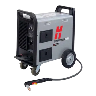
- Page 1 powermax 1650 Plasma Arc Cutting & Gouging System Operator Manual 804480 Revision 4...
- Page 2 Register your new Hypertherm system Register your product on-line at www.hypertherm.com/registration for easier technical and warranty support. You can also receive updates on new Hypertherm products and a free gift as a token of our appreciation. For your records Serial number:...
- Page 3 (P/N 804480) Revision 4 – November 2013 Hypertherm, Inc. Hanover, NH USA www.hypertherm.com © Copyright 2013 Hypertherm, Inc. All Rights Reserved Hypertherm and powermax are trademarks of Hypertherm, Inc. and may be registered in the United States and/or other countries.
- Page 4 55 11 2409 2636 Tel Hypertherm (S) Pte Ltd. 55 11 2408 0462 Fax 82 Genting Lane Media Centre Hypertherm México, S.A. de C.V. Annexe Block #A01-01 Avenida Toluca No. 444, Anexo 1, Singapore 349567, Republic of Singapore Colonia Olivar de los Padres 65 6841 2489 Tel Delegación Álvaro Obregón...
-
Page 5: Mains Supply
ELECTROMAGNETIC COMPATIBILITY (EMC) EMC Introduction b. Radio and television transmitters and receivers. Hypertherm’s CE-marked equipment is built in c. Computer and other control equip ment. compliance with standard EN60974-10. The equipment should be in stalled and used in d. Safety critical equipment, for example accordance with the information be low to guarding of industrial equipment. -
Page 6: Maintenance Of Cutting Equipment
Care should be taken to prevent the earthing of the work piece increasing the risk of injury to users, or damage to other elec tri cal equip ment. Where necessary, the con nec tion of the Hypertherm 4-08... -
Page 7: Warranty
- for any breach by Hypertherm of its ship, if Hypertherm is notified of a defect (i) with warranty. Distributors/OEMs may offer different respect to the power supply within a period of... - Page 8 Higher-level systems directives and standards. Only those versions of When a system integrator adds additional Hypertherm products with a CE Marking located equipment; such as cutting tables, motor drives, on or near the data plate have been tested for motion controllers or robots; to a Hypertherm...
-
Page 9: Patent Indemnity
Except only in cases of products not Hypertherm harmless in the event of any cause manufactured by Hypertherm or manufactured by a person other than Hypertherm not in strict of action arising from the use of the Products. conformity with Hypertherm’s specifications and... - Page 10 WARRANTY Hypertherm...
-
Page 11: Table Of Contents
TABLE OF CONTENTS Electromagnetic compatibility..........................i Warranty..................................iii Section 1 Safety Recognize safety information ...........................1-2 Follow safety instructions..........................1-2 Cutting can cause fire or explosion ........................1-2 Electric shock can kill............................1-3 Static electricity can damage circuit boards ....................1-3 Toxic fumes can cause injury or death......................1-4 A plasma arc can cause injury and burns......................1-5 Arc rays can burn eyes and skin........................1-5 Grounding safety..............................1-6... - Page 12 TABLE OF CONTENTS El choque eléctrico puede provocar la muerte..................1b-3 Electricidad estática puede dañar tablillas de circuito ................1b-3 Humos tóxicos pueden causar lesiones o muerte..................1b-4 El arco de plasma puede causar lesiones y quemaduras...............1b-5 Los rayos del arco pueden producir quemaduras en los ojos y en la piel ..........1b-5 Seguridad de toma a tierra..........................1b-6 Seguridad de los equipos de gas comprimido..................1b-6 Los cilindros de gas pueden explotar si están dañados .................1b-6...
- Page 13 TABLE OF CONTENTS ON/OFF pendant connection ........................3-12 Machine interface connection ......................3-12 Arc voltage...............................3-13 Changing XFER (start machine motion) from dry contact closure to voltage signal.....3-15 Section 4 Operation Controls and indicators .............................4-2 Indicator LEDs............................4-2 Install the consumables .............................4-3 T100 consumable configurations........................4-4 Shielded..............................4-4 Unshielded ..............................4-4 FineCut................................4-4...
- Page 14 TABLE OF CONTENTS powermax 1650 Operator Manual...
-
Page 15: Safety
Compressed gas equipment safety........................1-6 Gas cylinders can explode if damaged......................1-6 Noise can damage hearing ..........................1-7 Pacemaker and hearing aid operation......................1-7 A plasma arc can damage frozen pipes......................1-7 Additional safety information..........................1-7 Symbols and markings............................1-8 Warning labels ..............................1-9 Dry dust collection information........................1-11 Hypertherm 11/08... -
Page 16: Recognize Safety Information
WARNING CAUTION RECOGNIZE SAFETY INFORMATION The symbols shown in this section are used to Hypertherm uses American National Standards identify potential hazards. When you see a Institute guidelines for safety signal words and safety symbol in this manual or on your machine, symbols. -
Page 17: Electric Shock Can Kill
• Provide a disconnect switch close to the power • Each Hypertherm plasma system is designed to be supply with properly sized fuses. This switch allows used only with specific Hypertherm torches. Do not the operator to turn off the power supply quickly in substitute other torches which could overheat and an emergency situation. -
Page 18: Toxic Fumes Can Cause Injury Or Death
• Consult with a local expert to implement a site depends on site-specific variables such as: plan to ensure safe air quality. • Table design (wet, dry, underwater). • Material composition, surface finish, and composition of coatings. • Volume of material removed. Hypertherm 11/08... -
Page 19: A Plasma Arc Can Cause Injury And Burns
Less than 40 A 41 to 60 A 61 to 80 A 81 to 125 A 126 to 150 A 151 to 175 A 176 to 250 A 251 to 300 A 301 to 400 A 401 to 800 A Hypertherm 11/08... -
Page 20: Grounding Safety
• Never allow electrical contact between the plasma arc and a cylinder. • Never expose cylinders to excessive heat, sparks, slag or open flame. • Never use a hammer, wrench or other tool to open a stuck cylinder valve. Hypertherm 11/08... -
Page 21: Noise Can Damage Hearing
5. AWS F5.2, Recommended Safe Practices for Plasma Arc Cutting, American Welding Society, 550 LeJeune Road, P.O. Box 351040, Miami, FL 33135 6. CGA Pamphlet P-1, Safe Handling of Compressed Gases in Cylinders, Compressed Gas Association, 1235 Jefferson Davis Highway, Arlington, VA 22202 Hypertherm 11/08... -
Page 22: Symbols And Markings
SYMBOLS AND MARKINGS Your Hypertherm product may have one or more of the following markings on or near the data plate. Due to differences and conflicts in national regulations, not all marks are applied to every version of a product. -
Page 23: Warning Labels
3.2 Protect from shock by insulating yourself from Do not remove, destroy, or cover this label. work and ground. Replace if it is missing, damaged, or worn. 3.3 Disconnect power before servicing. Do not touch live parts. Hypertherm 11/08... -
Page 24: Warning Label
Button shirt collar. Protect ears from noise. Use welding helmet with the correct shade of filter. Become trained. Only qualified 110647 Rev. A www.hypertherm.com/weee personnel should operate this equipment. Use torches specified in the manual. Keep non-qualified personnel and children away. -
Page 25: Dust Collection Information
Note 2 – Users of Hypertherm manuals should consult and comply with all applicable federal, state, and local laws and regulations. Hypertherm does not, by the publication of any Hypertherm manual, intend to urge action that is not in compliance with all applicable regulations and standards, and this manual may never be construed as doing so. - Page 26 SAFETY Hypertherm 1-12 11/08...
-
Page 27: Section 1A
Les bouteilles de gaz comprimé peuvent exploser en cas de dommages ..........1a-6 Le bruit peut provoquer des problèmes auditifs ..................1a-7 Pacemakers et prothèses auditives ......................1a-7 Un arc plasma peut endommager les tuyaux gelés...................1a-7 Symboles et marquage............................1a-8 Étiquettes de sécurité............................1a-9 Information sur le dépoussiérage .......................1a-11 Hypertherm 1a-1 11/08... -
Page 28: Identifier Les Consignes De Sécurité
IDENTIFIER LES CONSIGNES DANGER AVERTISSEMENT ATTENTION DE SÉCURITÉ Hypertherm adopte les lignes directrices de l’American Les symboles indiqués dans cette section sont utilisés National Standards Institute relativement aux termes, aux pour identifier les risques éventuels. Si vous trouvez un symbole symboles et à... -
Page 29: Les Chocs Électriques Peuvent Être Fatals
Laisser la pièce à couper en place ou sur la Prévention des chocs électriques table de travail, le câble de retour connecté lors du Tous les systèmes plasma Hypertherm utilisent des hautes coupage. tensions pour le coupage (souvent de 200 à 400 V). On •... -
Page 30: Les Vapeurs Toxiques Peuvent Provoquer Des Blessures Ou La Mort
• Contrôler ou éprouver la qualité de l’air au site selon les besoins. • Consulter un expert local pour mettre en œuvre un plan du site afin d’assurer une qualité de l’air sûre. Hypertherm 1a-4 11/08... -
Page 31: L'arc Plasma Peut Provoquer Des Blessures Ou Des Brûlures
Moins de 40 A 41 à 60 A 61 à 80 A 81 à 125 A 126 à 150 A 151 à 175 A 176 à 250 A 251 à 300 A 301 à 400 A 401 à 800 A Hypertherm 1a-5 11/08... -
Page 32: Mise À La Masse Et À La Terre
• Ne jamais exposer des bouteilles à une chaleur excessive, aux étincelles, aux scories ou aux flammes nues. • Ne jamais utiliser des marteaux, des clés ou d’autres outils pour débloquer le robinet des bouteilles. Hypertherm 1a-6 11/08... -
Page 33: Le Bruit Peut Provoquer Des Problèmes Auditifs
• Ne pas s’enrouler le faisceau de la torche ou le câble de retour autour du corps. Les tuyaux gelés peuvent être endommagés ou éclater • Se tenir le plus loin possible de la source de courant. si l'on essaie de les dégeler avec une torche plasma. Hypertherm 1a-7 11/08... -
Page 34: Symboles Et Marquage
SÉCURITÉ SYMBOLES ET MARQUAGE Votre produit Hypertherm peut comporter une ou plusieurs des marques suivantes sur sa plaque signalétique ou à proximité. En raison des différends et des conflits relatifs aux règlements nationaux, toutes les marques ne sont pas appliquées à chaque version d’un produit. -
Page 35: Étiquette De Sécurité
Ne pas enlever, détruire ou couvrir cette étiquette. 3.2 Se protéger contre les chocs en s’isolant de la pièce La remplacer si elle est manquante, endommagée et de la terre. ou usée. 3.3 Couper l’alimentation avant d’entretenir. Ne pas toucher les pièces sous tension. Hypertherm 1a-9 11/08... -
Page 36: Étiquettes De Sécurité
Utiliser le masque de soudage avec le filtre ayant le bon indice 110647 Rev. A de protection. www.hypertherm.com/weee S’entraîner. Seul le personnel qualifié doit faire fonctionner cet équipement. Utiliser les torches prescrites dans le manuel. Tenir le personnel non qualifié et les enfants à... -
Page 37: Information Sur Le Dépoussiérage
à tous les systèmes de dépoussiérage. Note 2 – Les utilisateurs des manuels d’Hypertherm doivent consulter tous les règlements et lois fédéraux et locaux applicables et s’y conformer. Hypertherm n’a pas l’intention, en publiant un manuel d’Hypertherm, de demander des mesures qui ne sont pas conformes aux règlements et normes applicables et ce manuel ne peut jamais être interprété... - Page 38 SÉCURITÉ Hypertherm 1a-12 11/08...
-
Page 39: Seguridad
Los cilindros de gas pueden explotar si están dañados .................1b-6 El ruido puede deteriorar la audición ......................1b-7 Operación de marcapasos y de audífonos....................1b-7 Un arco plasma puede dañar tubos congelados ..................1b-7 Símbolos y marcas ............................1b-8 Etiquetas de advertencia ..........................1b-9 Información sobre la colección de polvo seco..................1b-11 Hypertherm 1b-1 11/08... -
Page 40: Reconocimiento De Información De Seguridad
PELIGRO ADVERTENCIA PRECAUCIÓN INFORMACIÓN DE SEGURIDAD Hypertherm usa las directivas del Instituto Americano de Los símbolos que se muestran en esta sección se Normas Nacionales (American National Standards Institute) utilizan para identificar los posibles peligros. Cuando vea para las palabras y símbolos que señalan seguridad. Las un símbolo de seguridad en este manual o en su máquina,... -
Page 41: El Choque Eléctrico Puede Provocar La Muerte
Prevención ante el electrochoque cortando. Deje la pieza en su lugar o sobre la mesa Todos los sistemas por plasma de Hypertherm usan alto de trabajo con el cable de trabajo conectado en voltaje en el proceso de corte (son comunes los voltajes todo momento. -
Page 42: Humos Tóxicos Pueden Causar Lesiones O Muerte
• Monitoree o compruebe la calidad del aire en el sitio reglamentos locales y nacionales. como fuera necesario. • Consulte con un experto local para realizar un plan al sitio para garantizar la calidad de aire seguro. Hypertherm 1b-4 11/08... -
Page 43: El Arco De Plasma Puede Causar Lesiones Y Quemaduras
Menos de 40 A 41 a 60 A 61 a 80 A 81 a 125 A 126 a 150 A 151 a 175 A 176 a 250 A 251 a 300 A 301 a 400 A 401 a 800 A Hypertherm 1b-5 11/08... -
Page 44: Seguridad De Toma A Tierra
• No exponga nunca los cilindros a calor excesivo, chispas, escorias o llamas. • No emplee nunca martillos, llaves u otro tipo de herramientas para abrir de golpe la válvula del cilindro. Hypertherm 1b-6 11/08... -
Page 45: El Ruido Puede Deteriorar La Audición
Se puede hacer daño a los tubos congelados, o se los • Manténgase tan lejos de la fuente de energía como puede reventar, si uno trata de descongelarlos con una sea posible. antorcha por plasma. Hypertherm 1b-7 11/08... -
Page 46: Símbolos Y Marcas
SÍMBOLOS Y MARCAS Su producto de Hypertherm puede tener una o más de las marcas que siguen en, o cerca de la placa de datos. Debido a diferencias y conflictos en reglamentos nacionales, no todas las marcas se aplican a toda versión del producto. -
Page 47: Etiquetas De Advertencia
3.1 Colóquese guantes aislantes. No utilice guantes dañados o mojados. No retire las etiquetas de advertencia ni las cubra con pintura. 3.2 Aíslese de la pieza de trabajo y de la tierra. Hypertherm 1b-9 11/08... -
Page 48: Etiqueta De Advertencia
Utilice protección para los oídos y abróchese el botón del cuello de la camisa. Utilice un casco de soldar 110647 Rev. A www.hypertherm.com/weee con el filtro de sombreado adecuado. Proteja su cuerpo completamente. Antes de trabajar en la máquina o de proceder a cortar, capacítese... -
Page 49: Información Sobre La Colección De Polvo Seco
Kst, índice de deflagración” y otros términos. Nota 1 – La interpretación de Hypertherm de estos nuevos requisitos es que, a no ser que se haya completado una evaluación específica del sitio para determinar que todo polvo generado no es combustible, la edición del 2007 de la NFPA 68 requiere el uso de respiraderos de explosión diseñados para el peor caso del valor Kst (vea anexo F) que... - Page 50 SEGURIDAD Hypertherm 1b-12 11/08...
-
Page 51: Specifications
Section 2 SPECIFICATIONS In this section: Power supply ..............................2-2 Duty cycle ..............................2-3 Dimensions and weight ..........................2-3 T100 torches ..............................2-4 Torch dimensions..............................2-5 T100 hand torch ............................2-5 T100M-2 machine torch.........................2-5 Symbols and markings............................2-6 S mark ...............................2-6 CE mark ..............................2-6 IEC symbols..............................2-6 powermax 1650 Operator Manual... -
Page 52: Power Supply
Drooping *Defined as a plot of output voltage versus output current Rated output current (I 30A – 100A Hypertherm Standard Rated Output 160 VDC Voltage (U Duty cycle (X*) at 104°F (40°C) at – Volts AC rms rated conditions (U... -
Page 53: Duty Cycle
SPECIFICATIONS Duty cycle Duty cycle is the percentage of time, during a 10 minute period, that the power supply can cut continuously. The diagram below depicts an 80% duty cycle. 8 minutes cutting 2 minutes resting Dimensions and weight 16.8 in (427 mm) 26.4 in (671 mm) -
Page 54: T100 Torches
SPECIFICATIONS T100 torches Handheld cutting capacity at 100 amps Recommended capacity 1-1/4 inch (32 mm) at 19 ipm (482 mm per min) Maximum capacity 1-1/2 inch (38 mm) at 10 ipm (250 mm per min) Severance capacity 1-3/4 inch (45 mm) at low speed Mechanized cutting capacity at 100 amps Recommended pierce capacity up to 1/2 inch (13 mm) -
Page 55: Torch Dimensions
SPECIFICATIONS Torch dimensions T100 hand torch 8.9" (226 mm) 1.5" (38 mm) 4.2" (107 mm) 2.55" (65 mm) 1.00" (25 mm) T100M-2 machine torch 1.00" 15.47" (25 mm) (393 mm) 2.35" 8" 1.38" (60mm) (203 mm) (35 mm) 32 pitch .125" (3.2 mm) width powermax 1650 Operator Manual... -
Page 56: Symbols And Markings
) constitutes a manufacturer’s declaration of conformity to applicable European directives and standards. Only those versions of Hypertherm products with a CE mark located on or near the data plate have been tested for compliance with the European Low Voltage Directive and the European EMC Directive. -
Page 57: Setup
Section 3 SETUP In this section: Upon receipt.................................3-2 Claims ..................................3-2 Contents of box ..............................3-2 Lifting the power supply ............................3-3 Locating the power supply..........................3-4 Power connection ...............................3-4 Engine drives .............................3-5 Grounding ................................3-6 Power cords .................................3-6 Three-phase power cord and plug installation .....................3-7 Power cord installation ..........................3-7 Torch installation..............................3-8 Plasma gas supply ............................3-10... -
Page 58: Upon Receipt
Claims for damage during shipment: If your unit was damaged during shipment, you must file a claim with the carrier. Hypertherm will furnish you with a copy of the bill of lading upon request. If you need additional assistance, call the nearest Hypertherm office listed in the front of this manual. -
Page 59: Lifting The Power Supply
SETUP Lifting the power supply WARNING • The system with torch weighs up to 150lb / 68 kg. • Always lift the power supply by TWO handles using two people or a hoist. • Do not lift the power supply by ONE han dle. •... -
Page 60: Power Connection
SETUP Locating the power supply Locate the Powermax1650 power supply with at least 10 inches (0.25 m) of open space at the front, back, and fan side of the power supply for proper ventilation. Power connection The Powermax1650 is a universal power supply that configures itself to operate with AC voltages from 200 to 600 3PH (230-400 3PH for the CE model). -
Page 61: Engine Drives
• Engine drive operation: 1. Set the engine drive output to 3 phase-AC. 2. Plug the Powermax1650 power cord into the power outlet. 3. Set the engine drive to the maximum output (see table below). • Use unshielded consumables if you experience difficulty cutting thicker material (CSA power supplies only). -
Page 62: Grounding
To ensure personal safety and proper operation, and to reduce electromagnetic interference (EMI), the Powermax1650 must be properly grounded through the power cord according to local and national electrical codes. Three-phase service must be of the 4-wire type with a green or green/yellow wire for protective earth ground and must comply with local and national electrical requirements. -
Page 63: Three-Phase Power Cord - Plug Installation
SETUP Three-phase power cord and plug installation The Powermax1650 power supplies are shipped with a 6 AWG 4-wire UL/CSA power cord on CSA units. A 10 mm2, 4-wire HAR power cord is provided on CE units. To operate the Powermax1650, use a plug that meets national or local electrical codes. The plug must be connected to the power cord by a licensed electrician. -
Page 64: Torch Installation
SETUP Torch installation 1. Turn OFF the power. 2. Remove the power cord from the power receptacle. 3. Open the Easy Torch Removal (ETR) door and route the lead through the end cap. ETR door End cap powermax 1650 Operator Manual... - Page 65 SETUP 4. Align the marks on the strain relief. 5. Pull back the quick-release collar and insert the lead’s gas fitting. Quick-release collar 6. Slide the quick-release collar foward to lock the gas fitting in place. Make sure that the gas fitting is secure.
-
Page 66: Plasma Gas Supply
SETUP Plasma gas supply The gas supply for the Powermax1650 can be shop-compressed air or cylinder-compressed air. A high-pressure regulator must be used on either type of supply and must be capable of delivering gas to the filter on the power supply at 550 scfh/9.2 scfm (260 l/min), minimum flow rate, at a minimum pressure of 90 psig (6.1 bar). -
Page 67: Gas Supply Installation
SETUP Gas supply installation Connect the air hose as follows: 1. Air fitting • For the standard model: Install a 1/4 NPT gas fitting on to the air filter inlet. The CE model provides a G1/4 adapter in the CE kit. Use liquid pipe sealant on the threads. -
Page 68: On/Off Pendant Connection
For the machine torch (T100), inputs for arc start are available through the machine interface connection on the rear of the power supply. Plug the Hypertherm remote pendant (see Section 5, Maintenance and parts, for part numbers) into the connector on the rear panel. -
Page 69: Arc Voltage
SETUP WARNING ELECTRIC SHOCK CAN KILL Disconnect electrical power before performing any maintenance. All work requiring removal of the power supply cover must be performed by a qualified technician. Arc voltage If arc voltage is necessary for activating a torch height control, the customer must supply an 18 AWG (1.0 mm2), single pair, unshielded cable rated for 300V or greater. - Page 70 SETUP 4. Find the power board. Use insulated type 1/4-inch faston terminal ends to connect to J15 and J16. Signal: Arc voltage (torch height control) Type: Output Notes: Full arc voltage. No voltage divider. 300 VDC maximum. (Signal not available on rear panel connector.) +VDC –VDC...
-
Page 71: Changing Xfer (Start Machine Motion) From Dry Contact Closure To Voltage Signal
SETUP Changing XFER (start machine motion) from dry contact closure to voltage signal 24 VDC (chassis ground reference) at 100ma max is available at J19 on the powerboard to drive an isolated/floating device such as a 24 VDC relay coil (240 ohms or greater) or a typical industrial isolated input module (which has an opto-coupler built-in). - Page 72 SETUP Driving an industrial isolated input module V-div – 6 V-div + Start Signal Isolated input Shield module J16 J15 – XFER START Notes: 1. Customer-supplied isolated input module. 2. Pins 5 and 6 are used only on Move the black (BLK) wire systems that include the to ground (GND) and add PowermaxEDGE cable with...
- Page 73 SETUP Driving a relay coil with an external power source 5 V-div – 6 V-div + Start Signal 24 VDC Shield – J16 J15 XFER START Notes: 1. Customer-supplied 24 VDC relay coil > 240 ohms. 2. Customer-supplied 24 VDC power source.
- Page 74 SETUP Driving an industrial isolated input module with an external power source 5 V-div – 6 V-div + Start signal 24 VDC Shield – Isolated input module J16 J15 XFER START – Notes: 1. Customer-supplied isolated input module. 2. Customer-supplied 24 VDC power source.
-
Page 75: Operation
Section 4 OPERATION In this section: Controls and indicators .............................4-2 Indicator LEDs............................4-2 Install the consumables .............................4-3 T100 consumable configurations........................4-4 Shielded..............................4-4 Unshielded ..............................4-4 FineCut................................4-4 Gouging ..............................4-5 T100M-2 consumable configurations ......................4-5 Shielded..............................4-5 FineCut................................4-6 Ohmic sensing retaining caps.......................4-6 Unshielded ..............................4-6 Set the mode switch............................4-7 Turn ON the power .............................4-7 Check the indicator lights..........................4-7 Adjust the gas pressure and current setting ....................4-8... -
Page 76: Controls And Indicators
OPERATION Controls and indicators ON (I) / OFF (0) switch Current (amps) adjustment / Mode switch AMPS gas test knob Pressure gauge Indicator LEDs Pressure regulator Indicator LEDs Green power ON LED When illuminated, indicates that power is applied to the system and the power switch is ON ( I ). -
Page 77: Install The Consumables
OPERATION Install the consumables WARNING Instant-On Torches PLASMA ARC CAN CAUSE INJURY AND BURNS The plasma arc comes on im me di ate ly when the torch switch is activated. The plasma arc will quickly burn through gloves and skin. Make sure the power is OFF before changing the consumables. -
Page 78: T100 Consumable Configurations
OPERATION T100 consumable configurations Shielded 120929 120928 120932 O-ring 058519 120926 120929 120928 120931 120925 120929 120928 120927 100A 220037 220051 220065 220048 220011 Unshielded The unshielded consumables available for the T100 hand torch (only for use with non-CE systems) are the same as those used for the T100M-2. -
Page 79: Gouging
OPERATION Gouging O-ring 058519 60A/80A 120977 120928 220059 120926 120925 100A 120977 220048 220063 220037 220051 T100M-2 consumable configurations Shielded 120930 120928 120932 O-ring 120930 120928 120931 058519 120926 120925 120930 120928 120927 100A 220047 220048 220011 220037 220051 powermax 1650 Operator Manual... -
Page 80: Finecut
OPERATION FineCut O-ring 30A – 50A 058519 220325* 120926 120925 220329 120928 120979 220061** 220404 * In CE countries, unshielded consumables may only be used in Ohmic sensing retaining caps** mechanized torch applications. Maintain a torch-to-work distance of 40A-80A 100A approximately 1/8 inch (3mm). -
Page 81: Set The Mode Switch
OPERATION Set the mode switch Use to cut expanded metal. Automatically reinitiates pilot. Use to cut plate/sheet metal. Optimum consumable life. Use to gouge, or for non-transfered-arc operation. Turn ON the power Position the power switch to ON ( I ) as shown. Note: The cooling fan is automatic and will only operate when needed. -
Page 82: Adjust The Gas Pressure And Current Setting
OPERATION Adjust the gas pressure and current setting AMPS Set the current knob to gas test. Push the regulator knob to lock it. AMPS Pull the regulator knob to unlock it. Set the cutting current (30 amps minimum). 35-50 ft 12-15 m 15-25 ft 4.5-7.5 m... -
Page 83: Hand Torch Operation
OPERATION Hand torch operation WARNING Instant-On Torches PLASMA ARC CAN CAUSE INJURY AND BURNS The plasma arc comes on im me di ate ly when the torch switch is activated. The plasma arc will quickly burn through gloves and skin. •... -
Page 84: Attach The Work Clamp
OPERATION WARNING SPARKS AND HOT METAL CAN INJURE EYES AND BURN SKIN When firing the torch at an angle, sparks and hot metal will spray out from the nozzle. Point the torch away from yourself and others. Attach the work clamp Attach the work clamp securely to the workpiece. -
Page 85: Hand Torch Cutting Technique
• For straight-line cuts, use a straight edge as a guide. To cut circles, use a template or the Hypertherm plasma cutting guide (part number 027668). • Postflow – After the torch trigger switch is released, the gas will continue to flow for 30 seconds to cool the torch and consumables. -
Page 86: Piercing
OPERATION Piercing WARNING SPARKS AND HOT METAL CAN INJURE EYES AND BURN SKIN When firing the torch at an angle, sparks and hot metal will spray out from the nozzle. Point the torch away from yourself and others. Hold the torch so that the nozzle is within 1/8 in (3 mm) from the workpiece before firing the torch. Fire the torch at an angle to the workpiece, then slowly rotate it to an upright position. -
Page 87: Gouging
OPERATION Gouging WARNING SPARKS AND HOT METAL CAN INJURE EYES AND BURN SKIN When firing the torch at an angle, sparks and hot metal will spray out from the nozzle. Point the torch away from yourself and others. Hold the torch so that the nozzle is within 1/16 in (1.5 mm) from the workpiece before firing the torch. -
Page 88: Cut Charts
OPERATION Cut charts 100 amp mechanized shielded consumables • Torch-to-work dis tance for the following cut chart is 1/8 in (3.2 mm) for all cuts. Shield Retaining cap Nozzle Electrode Swirl ring T100M-2 torch 220047 220048 220011 220037 220051 Mild steel Pierce Material thickness Maximum travel speed... - Page 89 OPERATION 80 amp mechanized shielded consumables • Torch-to-work dis tance for the following cut chart is 1/16 in (1.5 mm) for all cuts. Shield Retaining cap Nozzle Electrode Swirl ring T100M-2 torch 120930 120928 120927 120926 120925 Mild steel Maximum travel speed Optimum travel speed Pierce Material thickness...
- Page 90 OPERATION 60 amp mechanized shielded consumables • Torch-to-work dis tance for the following cut chart is 1/16 in (1.5 mm) for all cuts. Shield Retaining cap Nozzle Electrode Swirl ring T100M-2 torch 120930 120928 120931 120926 120925 Mild steel Pierce Material thickness Maximum travel speed Optimum travel speed...
- Page 91 OPERATION 40 amp mechanized shielded consumables • Torch-to-work dis tance for the following cut chart is 1/16 in (1.5 mm) for all cuts. Shield Retaining cap Nozzle Electrode Swirl ring T100M-2 torch 120930 120928 120932 120926 120925 Mild steel Pierce Maximum travel speed Optimum travel speed Material thickness...
-
Page 92: Finecut Consumables
OPERATION FineCut consumables • Torch-to-work dis tance for the following cut chart is 0.08 inches (2 032 mm) for mild steel and 0.010 inches (0.254 mm) for stainless steel. Deflector Retaining Nozzle Electrode Swirl ring T100M-2 torch 220325* 220329 120926 120925 120928 120979... - Page 93 OPERATION 100 amp mechanized unshielded consumables • Torch-to-work dis tance for the following cut chart is 3/16 in (4.8 mm) for all cuts. Deflector Retaining cap Nozzle Electrode Swirl ring T100M-2 torch 120979 220048 220064 220037 220051 Mild steel Pierce Material thickness Maximum travel speed Optimum travel speed...
- Page 94 OPERATION 40 to 60 amp mechanized unshielded consumables • Torch-to-work dis tance for the following cut chart is 1/16 inch (1.5 mm) for all cuts. Deflector Retaining cap Nozzle Electrode Swirl ring T100M-2 torch 120979 120928 220006 120926 120925 Mild steel Pierce Material thickness Maximum travel speed...
-
Page 95: Maintenance And Parts
Section 5 MAINTENANCE AND PARTS In this section: Routine maintenance............................5-2 Inspect the consumables........................5-3 Filter element replacement ........................5-4 Controls and indicators .............................5-5 Basic troubleshooting ............................5-6 System circuit diagram ............................5-9 Technical questions............................5-10 Parts..................................5-10 Torch parts ...............................5-10 Power supply parts ..........................5-11 Accessories.............................5-11 powermax 1650 Operator Manual... -
Page 96: Routine Maintenance
MAINTENANCE AND PARTS Routine maintenance WARNING ELECTRIC SHOCK CAN KILL Disconnect the electrical power before performing any maintenance. All work requiring removal of the power supply cover must be performed by a qualified technician. Each Use Check the consumables for Check the gas pressure. -
Page 97: Inspect The Consumables
MAINTENANCE AND PARTS Inspect the consumables Part Check for Action Roundness of through hole Nozzle Center hole Good Worn Replace Max. 1/32 inch Electrode (0.8 mm) Center surface Maximum pit depth Replace 1/32 inch (0.8 mm) Swirl ring External surfaces Damage or debris Replace Central bore (I.D.) -
Page 98: Filter Element Replacement
MAINTENANCE AND PARTS Filter element replacement 1. Disconnect the electrical power and the gas supply. Remove the filter bowl. A. Pull down and hold the black release tab. (If you do not see the tab, check the back of the filter bowl.) B. -
Page 99: Basic Troubleshooting
MAINTENANCE AND PARTS Basic troubleshooting Problem Cause / Solution 1. The ON/OFF power switch is set 1.1 The power cord is not plugged into the to I (ON), and the power ON power receptacle. (green) lamp is not illuminated. Plug the power cord into the receptacle. 1.2 The disconnect power switch is not set to ON or there is no power available to the disconnect power switch box. -
Page 100: Basic Troubleshooting
MAINTENANCE AND PARTS Basic troubleshooting (continued) Problem Cause / Solution 4. The power ON (green), 4.1 One of the internal thermostat switches temperature (yellow) and fault has opened due to overheating or (red) lamps are illuminated. extremely low temperature. Leave the power supply ON to allow the fan to cool the power supply (overheating). - Page 101 MAINTENANCE AND PARTS Basic troubleshooting (continued) Problem Cause / Solution 7. The arc blows out, but re-ignites 7.1 The consumable parts are worn or when the torch switch is pressed damaged. again. Inspect and change the con sum ables, as necessary.
- Page 102 MAINTENANCE AND PARTS Basic troubleshooting (continued) Problem Cause / Solution 10. The power ON (green) and fault 10.1 Self-diagnostic failure. (red) lamps are flashing. The system needs repair. 11.1 The start signal is ON when the ON/OFF 11. The power ON (green) and fault switch is activated.
-
Page 103: System Circuit Diagram
MAINTENANCE AND PARTS System circuit diagram powermax 1650 Operator Manual... -
Page 104: Technical Questions
If you are unable to fix a problem with your Powermax by following the steps in Basic troubleshooting in this section, or if you need further assistance: 1. Call your Hypertherm distributor or authorized Hypertherm repair facility. 2. Call the nearest Hypertherm Technical Service team listed in the front of this manual. Parts Torch parts 059264 T100 hand torch assembly, 25 ft (7.5 m) -
Page 105: Power Supply Parts
Replacement filter element 129654 ETR door assembly 129405 Consumable box 123654 20 ft ground clamp with cable and strain-relief 128750 Kit: Powermax1650 labels, CSA 128758 Kit: Powermax1650 labels, CE Accessories 128788 Stationary mounting kit 128647 Optional air filtration kit 011092... - Page 106 MAINTENANCE AND PARTS powermax 1650 5-12 Operator Manual...
Need help?
Do you have a question about the powermax1650 and is the answer not in the manual?
Questions and answers