Table of Contents
Advertisement
Quick Links
MELSECNET/H
Network Module
Thank you for purchasing the Mitsubishi programmable controller
MELSEC-Q Series.
Prior to use, please read both this manual and detailed manual
thoroughly and familiarize yourself with the product.
©2008 MITSUBISHI ELECTRIC CORPORATION
User's Manual
QJ71NT11B
MODEL
QJ71NT11B-U-HW
MODEL
CODE
IB(NA)-0800440-B(0903)MEE
(Hardware)
13JY93
Advertisement
Table of Contents

Related Manuals for Mitsubishi QJ71NT11B


Summary of Contents for Mitsubishi QJ71NT11B
- Page 1 MELSECNET/H Network Module User’s Manual (Hardware) QJ71NT11B Thank you for purchasing the Mitsubishi programmable controller MELSEC-Q Series. Prior to use, please read both this manual and detailed manual thoroughly and familiarize yourself with the product. MODEL QJ71NT11B-U-HW MODEL 13JY93 CODE IB(NA)-0800440-B(0903)MEE ©2008 MITSUBISHI ELECTRIC CORPORATION...
-
Page 2: Safety Precautions
SAFETY PRECAUTIONS (Read these precautions before using this product.) Before using this product, please read this manual and the relevant manuals carefully and pay full attention to safety to handle the product correctly. Precautionary notes in this manual cover only the installations of this product. For precautions on designing and discarding this product, refer to "Safety Precautions"... - Page 3 [Installation Precautions] CAUTION Use the programmable controller in the operating an environment that meets the general specifications given in the user's manual for the CPU module used. Failure to do so may result in electric shock, fire, malfunction, or damage to or deterioration of the product.
-
Page 4: Wiring Precautions
[Wiring Precautions] DANGER Shut off the external power supply for the system in all phases before wiring. Failure to do so may result in electric shock or damage to the product. CAUTION Ground the FG and LG terminals to the protective ground conductor dedicated to the programmable controller. - Page 5 This manual confers no industrial property rights or any rights of any other kind, nor does it confer any patent licenses. Mitsubishi Electric Corporation cannot be held responsible for any problems involving industrial property rights which may occur as a result of using the contents noted in this manual.
-
Page 6: Table Of Contents
CONTENTS 1. OVERVIEW ....................1 2. PERFORMANCE SPECIFICATIONS ............2 3. HANDLING ....................3 3.1 Handling Precautions ................4 4. PART NAME....................5 5. WIRING ......................7 5.1 Twisted Bus System (When using twisted pair cable) ......8 5.1.1 Specifications of twisted pair cable ............ 8 5.1.2 Precautions for wiring twisted pair cable .......... - Page 7 (1) For programmable controller system To configure a system meeting the requirements of the EMC and Low Voltage Directives when incorporating the Mitsubishi programmable controller (EMC and Low Voltage Directives compliant) into other machinery or equipment, refer to Chapter 9 "EMC AND LOW VOLTAGE DIRECTIVES"...
-
Page 8: Overview
1. OVERVIEW This manual explains how to handle the MELSECNET/H network module, model number QJ71NT11B (hereinafter referred to as the network module). The network module is used as a control/normal station in the PLC to PLC network in the MELSECNET/H system. -
Page 9: Performance Specifications
2. PERFORMANCE SPECIFICATIONS The following table shows the performance specifications for the network module: Specifications Item QJ71NT11B MELSECNET/H mode, MELSECNET/H Extended mode*1 Maximum number of link LX/LY 8192 points points per network 16384 points 16384 points • MELSECNET/H mode ≤... -
Page 10: Handling
3. HANDLING CAUTION Use the programmable controller in the operating an environment that meets the general specifications given in the user's manual for the CPU module used. Failure to do so may result in electric shock, fire, malfunction, or damage to or deterioration of the product. -
Page 11: Handling Precautions
3.1 Handling Precautions (1) Since the module case is made of resin, do not drop the module or apply a strong impact to it. (2) Do not remove the printed-circuit board of the module from the case. Doing so will cause failure. (3) Prevent foreign matter such as dust or wire chips from entering the module. -
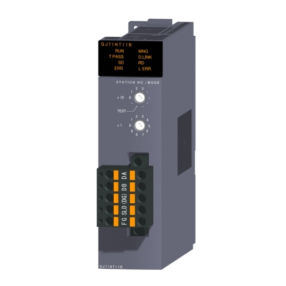
Page 12: Part Name
4. PART NAME <QJ71NT11B> (1) Indicator LED LED status Indication Green on Module operating normally Watchdog timer error (hardware error) Green on Operating as a control station or sub-control station Normal station (not operating as a control station or sub-control station) T. - Page 13 LED status Indication ERR. Red on • An error occurred, for instance a station number setting error, mode setting error (set to use prohibited), operation condition setting error (parameters), or an installed CPU type error (settings outside the range used, CPU type). •...
- Page 14 (2) Station number/Mode setting switches Used to set the station number and mode of the network module. (Factory default setting: 1) Set the same operation mode to all network modules. Setting Indication Setting error (The ERR. LED turns on.) 10 10s unit Station number 1 to 32 (online.) 1 1s unit 3 to 9...
-
Page 15: Wiring
5. WIRING DANGER Shut off the external power supply for the system in all phases before wiring. Failure to do so may result in electric shock or damage to the product. CAUTION Ground the FG and LG terminals to the protective ground conductor dedicated to the programmable controller. -
Page 16: Twisted Bus System (When Using Twisted Pair Cable)
5.1 Twisted Bus System (When using twisted pair cable) 5.1.1 Specifications of twisted pair cable The following shows the specifications of a shielded twisted pair cable used in the twisted bus system. Twisted pair cables that satisfy the following specifications can also be used even not introduced. -
Page 17: Precautions For Wiring Twisted Pair Cable
5.1.2 Precautions for wiring twisted pair cable (1) Wiring precautions (a) Wiring shielded twisted pair cable When wiring a shielded twisted pair cable, prevent the noise and surge induction, referring to the following. 1) Do not install a shielded twisted pair cable together with the main circuit, high-voltage cable, or load line and also do not bring them close to each other. -
Page 18: Twisted Bus System (When Using Cc-Link Ver. 1.10-Compatible Cable)10
The following table shows the specifications of the CC-Link Ver. 1.10-compatible cable used for the twisted bus system. The following CC-Link Ver. 1.10-compatible cables can be used. Product name Model Manufacturer Mitsubishi Electric System & Service Co., FANC-110SBH CC-Link Ver. Ltd. 1.10-compatible cables FA-CBL200PSBH... -
Page 19: Precautions For Wiring Cc-Link Ver. 1.10-Compatible Cable
5.2.2 Precautions for wiring CC-Link Ver. 1.10-compatible cable (1) Wiring precautions (a) Usage of CC-Link cables The CC-Link Ver. 1.10-compatible cable cannot be used together with other CC-Link cables (CC-Link dedicated cable and CC-Link dedicated high-performance cable) When used together, normal data communication cannot be expected. (b) Branching of CC-Link cable Connect network modules only with CC-Link cables. -
Page 20: Connecting Twisted Pair Cable, And Solderless Terminal For Cc-Link Ver.1.10-Compatible Cable
(1) Applicable solderless terminals and crimping tools Product name Model Manufacturer Remarks Solderless FA-VTC125T9 0.3 to 1.65mm For inquiries and orders, please terminal contact your local Mitsubishi Electric Engineering Co., Ltd Tool dedicated representative. for solderless FA-NH65A terminal Solderless TE0.5-10 For inquiries and orders, please 0.3 to 0.5mm... - Page 21 In the example, a crimping tool "FA-VTC125T9" manufactured by Mitsubishi Electric Corporation is used. 1) Strip the cable jacket by 5.5mm to 6.5mm. 2) Place the terminal in the correct place (in the end) of the locater.
-
Page 22: External Dimensions
6. EXTERNAL DIMENSIONS QJ71NT11B (0.91) 17.5 27.4 (3.54) (0.69) (1.08) Unit: mm (in.) - Page 23 MEMO...
- Page 24 Warranty Mitsubishi will not be held liable for damage caused by factors found not to be the cause of Mitsubishi; machine damage or lost profits caused by faults in the Mitsubishi products; damage, secondary damage, accident compensation caused by special factors unpredictable by Mitsubishi;...