Table of Contents
Advertisement
Quick Links
Thank you for purchasing the Mitsubishi programmable controller
MELSEC-Q series.
Prior to use, please read this and relevant manuals thorougly to fully
understand the product.
2007 MITSUBISHI ELECTRIC CORPORATION
C Controller
User's Manual
Q06CCPU-V-B
MODEL Q06CCPU-V-B-U-HW-J
MODEL
CODE
IB(NA)-0800404-C(0810)MEE
Module
(Hardware)
13JY52
Advertisement
Table of Contents

Subscribe to Our Youtube Channel
Related Manuals for Mitsubishi MELSEC-Q Q06CCPU-V-B


Summary of Contents for Mitsubishi MELSEC-Q Q06CCPU-V-B
- Page 1 C Controller Module User’s Manual (Hardware) Q06CCPU-V-B Thank you for purchasing the Mitsubishi programmable controller MELSEC-Q series. Prior to use, please read this and relevant manuals thorougly to fully understand the product. MODEL Q06CCPU-V-B-U-HW-J MODEL 13JY52 CODE IB(NA)-0800404-C(0810)MEE 2007 MITSUBISHI ELECTRIC CORPORATION...
- Page 2 SAFETY PRECAUTIONS (Always read these instructions before using this product.) Before using this product, please read this manual and the relevant manuals introduced in this manual carefully and pay full attention to safety to handle the product correctly. In this manual, the safety instructions are ranked as "DANGER" and "CAUTION". Indicates that incorrect handling may cause DANGER hazardous conditions, resulting in death or severe...
- Page 3 [DESIGN PRECAUTIONS] DANGER Provide a safety circuit outside the C Controller module to ensure that the entire system will operate safely even if an external power failure or C Controller module failure occurs. Failure to do so could result in accidents due to erroneous output or operation.
- Page 4 [DESIGN PRECAUTIONS] DANGER When controlling a running C Controller module (data modification) by connecting a personal computer to the C Controller module, create an interlock circuit on user programs so that the whole system functions safely all the time.This must be also done when performing any other controls (e.g. operating status change (status control)) or operations instructed from the computer.
- Page 5 [INSTALLATION PRECAUTIONS] CAUTION Use the C Controller module in an environment that meets the general specifications shown in this manual. Using this C Controller module in an environment outside the range of the general specifications could result in an electric shock, fire, erroneous operation, and damage to or deterioration of the product.
- Page 6 [WIRING PRECAUTIONS] CAUTION Be sure to ground the FG and LG terminals to the protective ground conductor. Not doing so could result in an electric shock or erroneous operation. Prevent foreign matter such as dust or wiring debris from entering the module.
- Page 7 [STARTUP AND MAINTENANCE PRECAUTIONS] DANGER Do not touch the terminals while power is on. Doing so may cause an electric shock. Correctly connect the battery. Also, do not charge, disassemble, heat, place in fire, short circuit, or solder the battery. Mishandling of the battery can cause overheating or cracks which could result in injury and/or fires.
- Page 8 [STARTUP AND MAINTENANCE PRECAUTIONS] CAUTION Completely turn off the externally supplied power used in the system before mounting or removing the module. Not doing so could result in module failure or malfunction. Do not mount/remove the module onto/from the base unit more than 50 times (IEC 61131-2 compliant), after the first use of the product.
- Page 9 This manual confers no industrial property rights or any rights of any other kind, nor does it confer any patent licenses. Mitsubishi Electric Corporation cannot be held responsible for any problems involving industrial property rights which may occur as a result of using the contents noted in this manual.
-
Page 10: Table Of Contents
CONTENTS 1. OVERVIEW ....................1 2. SPECIFICATIONS ..................4 2.1 General Specifications ................4 2.2 Performance Specifications..............6 3. MOUNTING AND INSTALLATION ..............8 3.1 Handling Precautions ................8 3.2 Fail-safe Circuit ..................10 4. PARTS NAMES AND FUNCTIONS ............. 19 4.1 Parts Names and Functions .............. - Page 11 About Manuals The following manuals are also related to this product. If necessary, please place an order referring to the table below. Related Manuals Manual Number Manual name (Model code) C Controller Module User's Manual This manual explains the features, specifications, functions and SH-080720ENG troubleshooting of the C Controller module.
-
Page 12: Overview
1. OVERVIEW (1) About this manual The C Controller module installation and wiring to other devices are described in this manual. This manual explains the C Controller module. Refer to the QCPU (Q mode) CPU Module User's Manual (Hardware) for the details of the C Controller system listed below.When referring to the manual, read the "CPU module"... - Page 13 Shield section Clamp fitting Masked Shield cable Recommended clamp fitting: Mitsubishi AD75CK Note) The method of earthing by soldering a wire onto the shield section of the shielded cable as shown below is not recommended. The high frequency impedance will increase and the shield will be ineffective.
- Page 14 (2) Included parts The following tables list the parts included with the C Controller module. Product Name Type Quantity C Controller Module Q06CCPU-V-B Battery Q6BAT This Manual (3) Generic terms and abbreviations used in this manual Unless otherwise specified, this manual uses the following generic terms and abbreviations to explain the Q06CCPU-V-B C Controller module.
-
Page 15: Specifications
2. SPECIFICATIONS 2.1 General Specifications The following indicates the general specifications of the C Controller module. Item Specifications Operating ambient 0 to 55 temperature Storage ambient -25 to 75 temperature Operating 5 to 95%RH , non-condensing ambient humidity Storage ambient 5 to 95%RH , non-condensing humidity... - Page 16 This indicates the section of the power supply to which the equipment is assumed to be connected between the public electrical power distribution network and the machinery within premises. Category II applies to equipment for which electrical power is supplied from fixed facilities.
-
Page 17: Performance Specifications
2.2 Performance Specifications This section explains the performance specifications of the C Controller module. Item Specifications Hardware specifications Endian format (Memory format) Big endian User file capacity (For Standard ROM 6M bytes user file storage) Work RAM (for OS, driver, user 64M bytes program execution) Battery-backed-up RAM... - Page 18 Item Specifications Number of I/O points (number of points accessible to actual I/O 4096 points (X/Y0 to FFF) modules) Year, month, day, hour, minute, second, day of week (automatic leap year detection) Clock function Clock accuracy: Daily error -10.89 to +8.64 seconds (0 to 55 Daily error -4.32 to +5.25 seconds (25 Permissible momentary stop time...
-
Page 19: Mounting And Installation
3. MOUNTING AND INSTALLATION 3.1 Handling Precautions This section explains the handling precautions for the C Controller module. CAUTION Use the C Controller module in an environment that meets the general specifications shown in this manual. Using this C Controller module in an environment outside the range of the general specifications could result in an electric shock, fire, erroneous operation, and damage to or deterioration of the product. - Page 20 (1) The casing of the C Controller module is made of resin.Do not drop it or not apply strong shock to it. (2) Do not remove the printed boards of the module from the casing. Doing so may cause a failure. (3) Tighten the module fixing screws and the RS-232 cable connector mounting screw within the following range.
-
Page 21: Fail-Safe Circuit
3.2 Fail-safe Circuit DANGER Provide a safety circuit outside the C Controller module to ensure that the entire system will operate safely even if an external power failure or C Controller module failure occurs. Failure to do so could result in accidents due to erroneous output or operation. - Page 22 DANGER If load current more than the rating or overcurrent due to a short circuit in the load has flowed in the output module for a long time, it may cause a fire and smoke. Provide an external safety device such as a fuse. Create the circuit so that the external power supply will turn on after the C Controller system is powered on.
- Page 23 When the C Controller system is powered ON-OFF, the control output may not be supplied normally for a little while because of the delay time and rise time difference between the C Controller system power supply and the external power supply for the control target (especially in DC). In the case of a DC output module, for example, when power is applied to the external power supply first and then the C Controller system power supply, the DC output module may temporarily generate false...
- Page 24 (1) System design circuit example (when not using contact of power supply module) Power supply For AC For AC/DC Power supply Transformer Transformer Transformer Fuse Fuse Fuse C Controller C Controller DC power RUN/STOP circuit module module Started when RA1 (-) (+) (control start output User...
- Page 25 Perform programming to execute the following operation at start-up of the C Controller module. Turning ON Ym when battery voltage drop is detected. Create a program so that Ym is turned ON by the QBF_Y_Out_BitEx function when the "Builtin battery error status" of the QBF_ReadStatusEx function turns to 1 (battery error occurrence).
- Page 26 (2) System design circuit example (when using contact of power supply module) Power supply For AC/DC Transformer Transformer Fuse Fuse C Controller RUN/STOP circuit DC power module Started when RA1 (-) (+) (control start output of C Controller Fuse module) turns ON. User program START SW...
- Page 27 Perform programming to execute the following operation at start of the C Controller module. Turning ON Ym when battery voltage drop is detected. Create a program so that Ym is turned ON by the QBF_Y_Out_BitEx function when the "Builtin battery error status" of the QBF_ReadStatusEx function turns to 1 (battery error occurrence).
- Page 28 Though Mitsubishi products are manufactured under strict quality control, the C Controller system may fail for unspecific reasons. To prevent mechanical damage and/or accidents in that case, please configure a fail-safe circuit outside the C Controller module.
- Page 29 <Fail-safe circuit example> On delay timer User program *2 Off delay timer External load 0.5s 0.5s 24VDC C Controller module Output module *3 Create a program so that Y80 alternates between ON and OFF at intervals of 0.5 s. (Use the QBF_Y_Out_BitEx function to turn Y80 ON/OFF.) Y80 repeats turning ON and then OFF at 0.5s intervals.
-
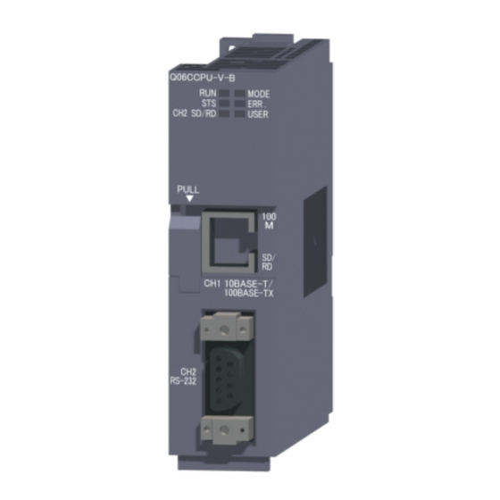
Page 30: Parts Names And Functions
4. PARTS NAMES AND FUNCTIONS 4.1 Parts Names and Functions The part names of the C Controller module are shown below. [Front view] [Front cover opened] STOP MODE RESET SEL. Put your finger here to open the front cover. [Side view]... -
Page 31: Led Indicator Specifications
Name Description 1) Indicator LEDs Refer to Section 4.2 for the indicator LEDs. Connector used to connect the C Controller module to 10BASE-T/100BASE-TX 10BASE-T/100BASE-TX. interface connector (The C Controller module determines 10BASE-T or (RJ45) 100BASE-TX depending on the target device.) RS-232 interface Connector used to connect the C Controller module to RS- connector... -
Page 32: In Normal Operation Mode (When The Mode Led Is Lit "Green")
4.2.1 In normal operation mode (When the MODE LED is lit "green") Change the operation mode by the switch.(Refer to Section 4.3) Description indicator status The C Controller module is in the RUN status. (Output (Y) from user program and writing to buffer memory are enabled) The C Controller module is in the STOP/PAUSE status. -
Page 33: In Hardware Self-Diagnostic Operation Mode (When The Mode Led Is Lit "Orange")
4.2.2 In hardware self-diagnostic operation mode (When the MODE LED is lit "orange") For the hardware self-diagnostic function, refer to the C Controller Module User's Manual. Change the operation mode by the switch. (Refer to Section 4.3) Name Description indicator status Hardware self-diagnostic mode MODE... -
Page 34: Switch Operation
4.3 Switch Operation 4.3.1 RUN/STOP/MODE switch operation STOP MODE Position Operation The C Controller module is operating. In normal operation (Output (Y) from user program and writing to buffer mode memory are enabled) In hardware self- For the hardware self-diagnostic function, refer to the diagnostic operation C Controller Module User's Manual. -
Page 35: Reset/Select Switch Operation
4.3.2 RESET/SELECT switch operation RESET SEL. Position Operation When holding RESET *1*2 All LEDs turn off and the hardware is reset. position Reset is canceled. The module starts up in either of the following operation modes depending on the RUN/STOP/MODE switch position. -
Page 36: External Wiring
5. EXTERNAL WIRING 5.1 10BASE-T/100BASE-TX Connection Sufficient safety precautions must be taken when installing the 100BASE-TX and 10BASE-T networks. Consult a specialist when connecting cable terminals or installing trunk line cables, etc. (1) Twisted pair cable Twisted pair cables are used for connection to 10BASE-T/ 100BASE-TX interfaces. - Page 37 POINT During the high speed communication (100Mbps) via 100BASE-TX connection, a communication error may occur due to high frequency noise generated from the device other than C Controller module, depending on the installation environment. When configuring the network system, take the following measures on the C Controller module side to eliminate the effect of high frequency noise.
-
Page 38: Rs-232 Connection
5.2 RS-232 Connection RS-232 cables are used for connection to RS-232 interfaces. (1) RS-232 connector specifications Signal direction Signal Signal name C Controller module abbreviation Modem CD(DCD) Data Carrier Detect RD(RXD) Received Data SD(TXD) Transmitted Data ER(DTR) Data Terminal Ready SG(GND) Signal Ground DR(DSR) - Page 39 (2) RS-232 interface connector The C Controller module uses the following RS-232 interface connector. • DDK Ltd. 9-pin D-sub (female) screw type 17L-10090-27 (D9AC) (-FA) Use the following as the connector shell of the connector cable of the C Controller module side. •...
- Page 40 (3) RS-232 cable Use the RS-232-compliant cable which length is 15m or less. [Recommended cable] 7/0.127 P HRV-SV... Specify the number of pairs in (For 13 pairs, specify 7/0.127 13P HRV-SV.) (Oki Electric Cable Company, Limited) (4) Precautions for wiring RS-232 cables Precautions for wiring RS-232 cables are shown below.
-
Page 41: External Dimensions
6. EXTERNAL DIMENSIONS 27.4 89.3 (3.52) (1.08) (0.21) STOP MODE RESET SEL. Cable's outside diameter 4+10 (Unit: mm (in.)) The bending radius near the connectors (reference value: R1) should be four times as long as the cable's outside diameter or more when connecting the twisted pair cable. -
Page 42: Transportation Precautions
7. TRANSPORTATION PRECAUTIONS When transporting lithium batteries, be sure to treat them based on the transportation regulations. 7.1 Applicable model The lithium battery used for the C Controller module is classified as shown in the table below. Product name Model name Description Handled as Non-... - Page 44 Warranty Mitsubishi will not be held liable for damage caused by factors found not to be the cause of Mitsubishi; machine damage or lost profits caused by faults in the Mitsubishi products; damage, secondary damage, accident compensation caused by special factors unpredictable by Mitsubishi;...
Need help?
Do you have a question about the MELSEC-Q Q06CCPU-V-B and is the answer not in the manual?
Questions and answers