Mitsubishi Q68TD-G-H01 User Manual
Melsec-q series channel isolated thermocouple input module
Hide thumbs
Also See for Q68TD-G-H01:
- User manual (226 pages) ,
- User manual (214 pages) ,
- User manual (218 pages)
Table of Contents
Advertisement
Quick Links
Download this manual
See also:
User Manual
Channel Isolated Thermocouple
Thank you for purchasing the Mitsubishi programmable controller
MELSEC-Q series.
Prior to use, please read this and relevant manuals thorougly to fully
understand the product.
© 2007 MITSUBISHI ELECTRIC CORPORATION
User's Manual
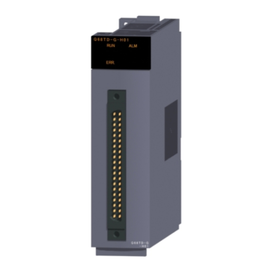
Q68TD-G-H01
MODEL Q68TD-G-H01-U-HW
MODEL
CODE
IB(NA)-0800389-B(0810)MEE
Input Module
(Hardware)
13JY36
Advertisement
Table of Contents

Subscribe to Our Youtube Channel
Related Manuals for Mitsubishi Q68TD-G-H01


Summary of Contents for Mitsubishi Q68TD-G-H01
- Page 1 Channel Isolated Thermocouple Input Module User’s Manual (Hardware) Q68TD-G-H01 Thank you for purchasing the Mitsubishi programmable controller MELSEC-Q series. Prior to use, please read this and relevant manuals thorougly to fully understand the product. MODEL Q68TD-G-H01-U-HW MODEL 13JY36 CODE IB(NA)-0800389-B(0810)MEE...
- Page 2 SAFETY PRECAUTIONS (Read these precautions before use.) Before using this product, please read this manual and the relevant manuals introduced in this manual carefully and pay full attention to safety to handle the product correctly. The instructions given in this manual are concerned with this product. For the safety instructions of the programmable controller system, please read the User’s Manual for the CPU module.
- Page 3 CAUTION Do not bunch the control wires or communication cables with the main circuit or power wires, or install them close to each other. They should be installed 100 mm (3.94 inch) or more from each other. Not doing so could result in noise that may cause malfunction. [INSTALLATION PRECAUTIONS] CAUTION Use the programmable controller in the environment conditions given in the...
- Page 4 [WIRING PRECAUTIONS] CAUTION Always ground the shielded cables for the programmable controller. There is a risk of electric shock or malfunction. For wiring and connection, properly press, crimp or solder the connector with the tools specified by the manufactures and attach the connector to the module securely.
- Page 5 This manual confers no industrial property rights or any rights of any other kind, nor does it confer any patent licenses. Mitsubishi Electric Corporation cannot be held responsible for any problems involving industrial property rights which may occur as a result of using the contents noted in this manual.
-
Page 6: Table Of Contents
CONTENTS 1. OVERVIEW ....................1 1.1 Restrictions on mountable slot position ............ 1 2. PERFORMANCE SPECIFICATIONS ............. 3 3. IMPLEMENTATION AND INSTALLATION............. 6 3.1 Handling Precautions ................6 3.2 Installation Environment ................6 4. PART NAMES ....................7 5. WIRING ......................9 5.1 Wiring Precautions ................... - Page 7 (1) For programmable controller system To configure a system meeting the requirements of the EMC and Low Voltage Diretives when incorporating the Mitsubishi programmable controller (EMC and Low Voltage Directives compliant) into other machinery or equipment, refer to Chapter 9 "EMC AND LOW VOLTAGE DIRECTIVES"...
-
Page 8: Overview
Q68TD-G-H01 with a combination of the power supply module and the base unit. For the slot that the Q68TD-G-H01 cannot be mounted, leave the slot open or mount a module other than the Q68TD-G-H01. The Q68TD-G-H01 has no restrictions of the combination between a power supply module and a base unit other than the combination listed below. - Page 9 Not mountable Mountable Power Slot Slot Slot supply No.0 No.1 No.2 I/01 I/01 Figure 1.1 Mountable slot position of Q68TD-G-H01 Not mountable Mountable Power Slot Slot Slot supply No.0 No.1 No.2 I/01 I/01 Figure 1.2 Mountable slot position of Q68TD-G-H01...
-
Page 10: Performance Specifications
2. PERFORMANCE SPECIFICATIONS The following are the performance specifications of the Q68TD-G-H01. (1) Performance specification list Table 2.1 List of performance specifications Item Specifications Number of channels 8 channels Temperature 16-bit signed binary (-2700 to 18200) conversion value Output Scaling value... - Page 11 *1 The Q68TD-G-H01 needs to be powered for 30 minutes warm-up in order to satisfy with the accuracy. *2 Calculate the accuracy in the following method. (Accuracy) = (conversion accuracy) + (temperature characteristic) (operating ambient temperature variation) + (cold junction temperature compensation accuracy) An operating ambient temperature variation indicates a deviation of the operating ambient temperature from the range.
- Page 12 *2 The accuracies only in the temperature ranges of Class 1 to 3 (shaded areas) in JIS C1602-1995 apply. Also, the Q68TD-G-H01 needs to be powered for 30 minutes warm-up in order to satisfy with the accuracy. *3 Temperature measurement can be executed, but accuracy is not guaranteed.
-
Page 13: Implementation And Installation
3. IMPLEMENTATION AND INSTALLATION 3.1 Handling Precautions (1) Do not drop or give a strong impact to the case. (2) Do not remove the printed-circuit board of the module from the case. Doing so may cause a failure. (3) Prevent foreign matter such as dust or wire chips from entering the module. -
Page 14: Part Names
4. PART NAMES The following explains the part names of the Q68TD-G-H01. (Connector (Connector terminal terminal number) number) Figure 4.1 Part names Table4.1 Part names Number Name Description Displays the operating status of the Q68TD-G-H01. : Normal operation RUN LED... - Page 15 Table4.2 Signal name Terminal Terminal Signal name Signal name number number CH1+ CH1- CH2+ CH2- CH3+ CH3- CH4+ CH4- CH5+ CH5- CH6+ CH6- CH7+ CH7- CH8+ CH8- RTD+ Seen from the front RTDG RTD- of the module *For actual wiring, refer to Section 5.2 External Wiring.
-
Page 16: Wiring
Q68TD-G-H01. (1) Use separate cables for the AC control circuit and the external input signals of the Q68TD-G-H01 to avoid the influence of the AC side surges and inductions. (2) Always place the thermocouple at least 100mm away from the main circuit cables and AC control circuit lines. -
Page 17: External Wiring
*4 When connecting the RTD, always connect the terminals between RTD- and RTD G. Figure 5.1 Wiring procedure POINT The Q68TD-G-H01 needs to be powered for 30 minutes warm-up in order to satisfy with the accuracy. Moreover, the Q68TD-G-H01 needs to be powered for 30 minutes warm-up when the offset/gain setting is performed and after the online module replacement is performed. -
Page 18: Intelligent Function Module Switch Settings
5.3 Intelligent Function Module Switch Settings (1) Setting item Intelligent function module switch has switches 1 to 5.The setting is executed with 16-bit data. When not setting the intelligent function module switch, the default of switches 1 to 5 is 0. Table 5.1 Intelligent function module switch settings Setting item Thermocouple type... -
Page 19: External Dimensions
6. EXTERNAL DIMENSIONS 90 (3.54) 47 (1.85) 137 (5.39) 27.4 (1.08) Unit : mm(in.) - Page 20 Warranty Mitsubishi will not be held liable for damage caused by factors found not to be the cause of Mitsubishi; machine damage or lost profits caused by faults in the Mitsubishi products; damage, secondary damage, accident compensation caused by special factors unpredictable by Mitsubishi;...
Need help?
Do you have a question about the Q68TD-G-H01 and is the answer not in the manual?
Questions and answers