Table of Contents
Advertisement
Quick Links
Advertisement
Table of Contents

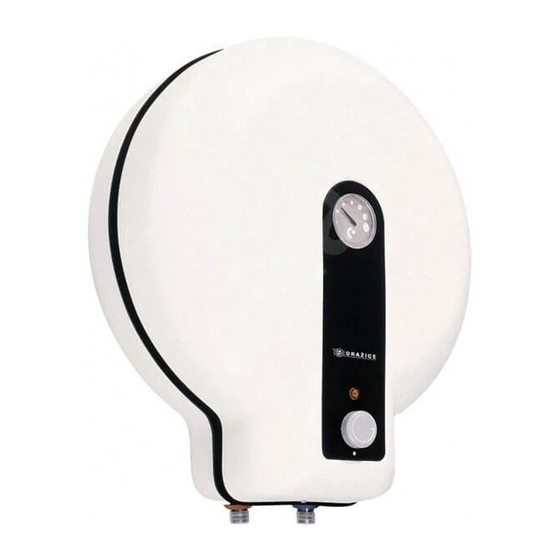
Summary of Contents for Drazice TO-20
-
Page 1: Installation Manual
OPERATING AND INSTALLATION MANUAL ELECTRIC ACCUMULATION WATER HEATER TO - 2060-SMART Družstevní závody Dražice-strojírna s.r.o. (Works Cooperative - Dražice - Machine Plant, Ltd.) Dražice 69, 294 71 Benátky nad Jizerou tel.: +420 / 326 370 911 fax: +420 / 326 370 980 e-mail: export@dzd.cz... -
Page 2: Table Of Contents
CONTENTS TECHNICAL SPECIFICATION OF PRODUCT ....................4 FUNCTION DESCRIPTION ........................4 ADVICE FOR CUSTOMERS ........................4 1.2.1 HOT WATER CONSUMPTION ..................... 4 1.2.2 ENERGY SAVING ......................... 4 1.2.3 EMERGENCY POWER CONSUMPTION ..................4 DESIGN AND GENERAL HEATER DIMENSIONS ................... 5 OPERATION AND FITTING INSTRUCTIONS .................... - Page 3 READ CAREFULLY THE BELOW INSTRUCTIONS PRIOR TO THE INSTALLATION THE HEATER! Dear Customer, The Works Cooperative of Dražice - Machine Plant, Ltd., would like to thank you for your decision to use a product of our brand. With this guide, we will introduce you to the use, construction, maintenance and other information on electrical water heaters.
-
Page 4: Technical Specification Of Product
1 TECHNICAL SPECIFICATION OF PRODUCT 1.1 FUNCTION DESCRIPTION After the heater is connected to electric network, the heating element starts heating water. The element is turned on and off by a thermostat. Thermostat can be set as per your need within the range from 7°C to 74°C. We recommend setting service water to max temperature of 60°C. -
Page 5: Design And General Heater Dimensions
TYPE TO - 20 UNIT HEAT LOSS [Wh/24h/l] NOMINAL CAPACITY [l] TIME OF CONTENT HEATING BY 50°C [hours] ELECTRICITY CONSUMPTION FOR HEATING OF THE CONTENTS FROM LOAD PROFILE DAILY ELECTRICITY CONSUMPTION 2.24 [kWh] MIXED WATER V40 [l] 26.92 Table 1 1.3 DESIGN AND GENERAL HEATER DIMENSIONS The heater tank is made of a steel plate and tested by 0.9 MPa overpressure. -
Page 6: Operation And Fitting Instructions
2 OPERATION AND FITTING INSTRUCTIONS 2.1 OPERATING CONDITIONS The tank shall only be used in accordance with the conditions specified on the performance plate and in instructions for electric wiring. Besides legally acknowledged national regulations and standards, also conditions for connection defined in local electric and water works have to be adhered to, as well as the installation and operation manual. - Page 7 TO 20 1/2" outer Figure 2 PARAMETER VALUE RATED PRESSURE [MPa] CAPACITY [l] VOLTAGE/FREQUENCY [V/Hz] 230/50 POWER INPUT [W] 2200 DIAMETER OF THE HEATER [mm] HEIGHT OF THE HEATER [mm] WEIGHT [kg] EL. PROTECTION IP 44 HEAT LOSSES/ENERGY EFFICIENCY 0.28 CLASS [kWh/24h] TIME OF EL.
-
Page 8: Plumbing Fixture
If the hot water heater is mounted in a tight, small space, or in an intermediate ceiling, etc., you have to make sure that the connecting side of the appliance (connections to water supply, area for electric plugging) remained accessible and no heat accumulation occurs. Free space of up to 600 mm from the bottom edge of the heater has to be available under the heater. - Page 9 Figure 3 SAFETY VALVE ADMISSIBLE MAX. PRESSURE IN STARTING OPERATING THE COLD WATER PRESSURE WATER HEATER PIPE [MPa] [MPa] PRESSURE [MPa] to 0. 4 8 to 0.546 to 0.8 Table 3 Heaters must be provided with a discharge valve mounted on the cold service water inlet to the heater for potential disassembly or repair.
-
Page 10: Electric Wiring
2.4 ELECTRIC WIRING 2.4.1 ELECTRIC INSTALLATION GENERAL INFORMATION The electric wiring scheme is attached to the water heater on the inner side of the removable front guard (Figure 4). The degree of protection of electric parts of the heater is IP 44. Power input of electric element is 2200 W. -
Page 11: Putting Out Of Service, Discharge
During the heating process the pressurised connection water that increases its volume due to heating must drip off the safety valve. In non-pressurised connection water drips off the overflow combination faucet. When heating is finished, the set temperature and the actual temperature of consumed water should be roughly equal. -
Page 12: Inspection, Maintenance & Care For The Appliance
2.7 INSPECTION, MAINTENANCE & CARE FOR THE APPLIANCE During the heating process the water that increases its volume during the heating must drip off the safety valve outlet (in non-pressurised connection this water drips off the combination faucet valve). In full heating (about 65 C) the volumetric water gain is approx. -
Page 13: Most Frequent Function Failures And Their Causes
2.8 MOST FREQUENT FUNCTION FAILURES AND THEIR CAUSES FAILURE SYMPTOM SOLUTION Water in tank is cold • Heating element failure • LED is on Water in the tank is not • Heating element failure LED is on warm enough • •... -
Page 14: Disposal Of Packaging Material And Functionless Product
Both the electric and water installation must follow and meet the requirements and regulations relevant in the country of use! We would like to emphasise that the heater must not be connected to power supply if work involving flammable liquids (petrol, spot remover) or gases, etc., is performed nearby.


Need help?
Do you have a question about the TO-20 and is the answer not in the manual?
Questions and answers