Table of Contents
Advertisement
Quick Links
Advertisement
Table of Contents

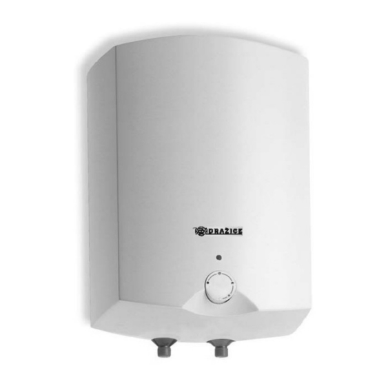
Summary of Contents for Drazice TO 10 IN
- Page 1 Operation and Installation Manual ELECTRIC WATER HEATER TO 5 IN/UP TO 10 IN/UP TO 15 IN/UP Družstevní závody Dražice – strojírna s.r.o. (Works Cooperative - Dražice – Machine Plant, Ltd.) Dražice 69 29471 Benátky nad Jizerou Tel.: 326 370 911, fax: 326 370 980 www.dzd.cz...
-
Page 2: Table Of Contents
Read carefully the below instructions prior to the installation of the water heater. INFORMATION LEAFLET pursuant to Directive No. 442//2004 Coll., and Annex No.7 Heater types Energy Heat Nominal Time of Electricity Heat losses efficiency losses capacity content consumption kWh/24hr class Wh/24hr/l heating... -
Page 3: Product Accessories
PRODUCT ACCESSORIES The product is packed together with service instructions and list of servicing organisations. The heater is equipped with a safety valve as a protective element. The valve is mounted on the cold water supply (see chapter 7). The package contains anchors and fasteners to fix the heater. -
Page 4: Plumbing Fixture
PLUMBING FIXTURE Water inflow and outflow is indicated with different colour terminals on the heater tubes. Cold water supply is indicated with blue and hot water outflow is indicated with red. There are two ways of connecting the water heater to water network. -
Page 5: Electrical Installation
For proper safety valve operation, a backflow valve must be mounted on the inlet pipes, preventing spontaneous heater draining and hot water penetrating back into the water main. We recommend that the hot water distribution from the heater was as short as possible to minimise heat losses. Safety valve starting Admissible operating Max pressure in the... -
Page 6: Functional Defects
FUNCTIONAL DEFECTS Defect Failure Water in the tank is cold LED is on - Heating element failure 2. Water in the tank is not warm enough LED is on - Heating element failure 3. Water in the tank is cold LED is not on - operating thermostat failure Safety thermostat shut off... -
Page 7: Installation Regulations
Both electric and water installation must follow and meet requirements and regulations relevant in the country of use. Fig. 1 Heater dimensions The “above-supply-point” version The “below-supply-point” version TO 5 UP TO 5 IN TO 10 UP TO 10 IN TO 15 UP TO 15 IN... - Page 8 Fig. 2 Wiring scheme Explanation: 1 - Thermostat 2 - Thermal fuse, non-reversible 3 - Heating element 4 - Operation indicator 5 – Terminal board L – Phase conductor N – Null conductor – – Earth conductor 04-2012...


Need help?
Do you have a question about the TO 10 IN and is the answer not in the manual?
Questions and answers