Drazice OKC 160 NTR/BP Operating And Installation Manual
Stationary hot water tank
Hide thumbs
Also See for OKC 160 NTR/BP:
- Operating and installation manual (33 pages) ,
- Operation and installation manual (29 pages) ,
- Operating and installation instruction manual (28 pages)
Table of Contents
Advertisement
Quick Links
- 1 Installation Manual
- 2 Operating and Installation Manual for Types: Okc 160 Ntr/Bp, Okc 200 Ntr/Bp, Okc 250 Ntr/Bp, Okc 200 Ntrr / Bp, Okc 250 Ntrr / Bp
- 3 Construction and Basic Dimensions of Tank
- 4 Operating and Installation Manual for Types: Okc 300 Ntr / Bp, Okc 400 Ntr / Bp, Okc 500 Ntr / Bp, Okc 300 Ntrr / Bp, Okc 400 Ntrr / Bp, Okc 500 Ntrr / Bp
- 5 Examples of Tanks Connection
- 6 Tank Cleaning and Anode Rod Exchange
- 7 Spare Parts
- Download this manual
See also:
Operation & Installation Manual
OPERATING AND
INSTALLATION MANUAL
STATIONARY HOT WATER TANKS
OKC 160 NTR/BP
OKC 200 NTR/BP
OKC 250 NTR/BP
OKC 200 NTRR/BP
OKC 250 NTRR/BP
Družstevní závody Dražice - strojírna s.r.o.
Dražice 69, 294 71 Benátky nad Jizerou
Phone.: +420 /326 370 990
Fax: +420 / 326 370 980
e-mail: prodej@dzd.cz
OKC 300 NTR/BP
OKC 300 NTRR/BP
OKC 400 NTR/BP
OKC 400 NTRR/BP
OKC 500 NTR/BP
OKC 500 NTRR/BP
OKC 750 NTR/BP
OKC 750 NTRR/BP
OKC 1000 NTR/BP
OKC 1000 NTRR/BP
Advertisement
Table of Contents

Related Manuals for Drazice OKC 160 NTR/BP


Summary of Contents for Drazice OKC 160 NTR/BP
-
Page 1: Installation Manual
OPERATING AND INSTALLATION MANUAL STATIONARY HOT WATER TANKS OKC 160 NTR/BP OKC 300 NTR/BP OKC 750 NTR/BP OKC 200 NTR/BP OKC 300 NTRR/BP OKC 750 NTRR/BP OKC 250 NTR/BP OKC 400 NTR/BP OKC 1000 NTR/BP OKC 200 NTRR/BP OKC 400 NTRR/BP... -
Page 2: Table Of Contents
CONTENTS PRODUCT TECHNICAL SPECIFICATION ....................... 4 FUNCTION DESCRIPTION ........................4 OPERATING AND INSTALLATION MANUAL FOR TYPES: OKC 160 NTR/BP, OKC 200 NTR/BP, OKC 250 NTR/BP, OKC 200 NTRR / BP, OKC 250 NTRR / BP ................4 1.2.1 PRODUCT DESCRIPTION......................4 1.2.2... - Page 3 PRIOR TO THE INSTALLATION OF THE TANK, READ CAREFULLY THIS MANUAL! Dear customer, The Works Cooperative of Dražice – Machine Plant, Ltd., would like to thank you for your decision to use a product of our brand. The present instructions will introduce you to the use, construction, maintenance and other information regarding electrical water tanks.
-
Page 4: Product Technical Specification
The time it takes to heat up using the heat exchanger depends on the temperature and flow of water in the hot water heating system. OPERATING AND INSTALLATION MANUAL FOR TYPES: OKC 160 NTR/BP, OKC 200 NTR/BP, OKC 250 NTR/BP, OKC 200 NTRR / BP, OKC 250 NTRR / BP 1.2.1 PRODUCT DESCRIPTION The tank receptacle is welded from a steel plate;... -
Page 5: Construction And Basic Dimensions Of Tank
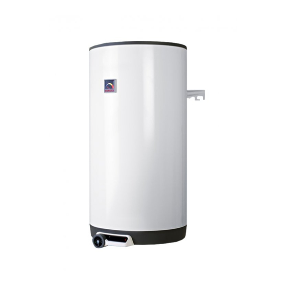
1.2.2 CONSTRUCTION AND BASIC DIMENSIONS OF TANK OKC 160 NTR/BP neck # 1 3/4" outer neck # 2 1" outer neck # 3 3/4" inner neck # 4 1/2" inner Figure 1 OKC 160 NTR/BP 1047 Table 1 - 5 -... - Page 6 OKC 200 NTR/BP, OKC 250 NTR/BP, OKC 200 NTRR/BP, OKC 250 NTRR/BP Figure 2 neck # 1 3/4" outer neck # 2 1" outer neck # 3 3/4" inner neck # 4 1/2" inner neck # 5 6/4" inner OKC 200 NTR/BP OKC 200 NTRR/BP OKC 250 NTR/BP OKC 250 NTRR/BP...
-
Page 7: Technical Parameters
1.2.3 TECHNICAL PARAMETERS OKC 160 OKC 200 OKC 200 OKC 250 OKC 250 MODEL NTR/BP NTR/BP NTRR/BP NTR/BP NTRR/BP VOLUME [l] WEIGHT WITHOUT WATER [kg] MAXIMUM TANK PRESSURE [MPa] OPERATING EXCHANGER PRESSURE [MPa] MAX. TEMPERATURE OF HEATING WATER [°C] WARM WATER MAXIMUM TEMPERATURE [°C] HEATING SURFACE OF BOTTOM 1.45... -
Page 8: Operating And Installation Manual For Types: Okc 300 Ntr / Bp, Okc 400 Ntr / Bp, Okc 500 Ntr / Bp, Okc 300 Ntrr / Bp, Okc 400 Ntrr / Bp, Okc 500 Ntrr / Bp
1.3 OPERATING AND INSTALLATION MANUAL FOR TYPES: OKC 300 NTR / BP, OKC 400 NTR / BP, OKC 500 NTR / BP, OKC 300 NTRR / BP, OKC 400 NTRR / BP, OKC 500 NTRR / BP 1.3.1 PRODUCT DESCRIPTION The tank receptacle is welded from a steel plate;... -
Page 9: Design And Basic Dimensions Of Tank
1.3.2 DESIGN AND BASIC DIMENSIONS OF TANK OKC 300 NTR/BP, OKC 300 NTRR/BP neck # 1 1" outer neck # 2 1/2" inner neck # 3 3/4" inner neck # 4 6/4" inner Figure 3 OKC 300 NTR/BP OKC 300 NTRR/BP 1558 1558 1579... - Page 10 OKC 400 NTR/BP, OKC 400 NTRR/BP, OKC 500 NTR/BP, OKC 500 NTRR/BP neck # 1 1" outer neck # 2 3/4" outer neck # 3 1/2" inner neck # 4 3/4" inner neck # 5 6/4" inner Figure 4 * at NTR neck #3 3/4" inner, neck #4 1/2" inner TYPE OKC 400 NTR/BP OKC 400 NTRR/BP...
-
Page 11: Technical Parameters
1.3.3 TECHNICAL PARAMETERS OKC 300 OKC 300 OKC 400 OKC 400 OKC 500 OKC 500 MODEL NTR/BP NTRR/BP NTR/BP NTRR/BP NTR/BP NTRR/BP VOLUME [l] WEIGHT WITHOUT WATER [kg] MAXIMUM TANK PRESSURE [MPa] OPERATING EXCHANGER PRESSURE [MPa] MAX.TEMPERATURE OF HEATING WATER [°C] WARM WATER MAXIMUM TEMPERATURE [°C]... -
Page 12: 750 Ntrr / Bp, Okc 1000 Ntrr / Bp
1.4 OPERATING AND INSTALLATION MANUAL FOR TYPES: OKC 750 NTR / BP, OKC 1000 NTR / BP, OKC 750 NTRR / BP, OKC 1000 NTRR / 1.4.1 PRODUCT DESCRIPTION The tank receptacle is welded from a steel plate; the exchangers from a steel tube and, as a unit, it is entirely coated with hot water resistant enamel. -
Page 13: Design And Basic Dimensions Of Tank
1.4.2 DESIGN AND BASIC DIMENSIONS OF TANK OKC 750 NTR/BP, OKC 1000 NTR/BP Figure 5 OKC 750 NTR/BP OKC 1000 NTR/BP neck # 1 5/4" outer neck # 2 3/4" outer 2030 2050 neck # 3 6/4" inner 1030 1130 neck # 4 1/2"... - Page 14 OKC 750 NTRR/BP, OKC 1000 NTRR/BP Figure 6 OKC 750 NTRR/BP OKC 1000 NTRR/BP neck # 1 1" outer neck # 2 3/4" outer 2030 2050 neck # 3 5/4" outer 1030 1130 neck # 4 1/2" inner max. 1140 max.
-
Page 15: Technical Parameters
1.4.3 TECHNICAL PARAMETERS OKC 750 OKC 1000 OKC 750 OKC 1000 MODEL NTR/BP NTR/BP NTRR/BP NTRR/BP TANK CAPACITY 1010 DIAMETER 1010 WEIGHT HOT WATER OPERATING PRESSURE HEATING WATER OPERATING PRESSURE MAX TEMPERATURE OF HEATING °C WATER MAX TEMPERATURE OF HOT °C WATER UPPER EXCHANGER HEAT... -
Page 16: Operation And Fitting Instructions
10 mm range. 2.2 ELECTRICAL INSTALLATION Wiring for: OKC 160 NTR/BP, OKC 200 NTR/BP, OKC 200 NTRR/BP, OKC 250 NTR/BP, OKC 250 NTRR/BP Water tank must be equipped with a universal electric heating unit with either set or adjustable heating element performance. -
Page 17: Technical Parameters Of Electric Heating Units
2.2.1 TECHNICAL PARAMETERS OF ELECTRIC HEATING UNITS Heating unit 2.2 Multipurpose heating unit 3 - 6 kW OUTPUT kW 1 PE-N AC 1 PE-N AC 2 PE-N AC 3 PE-N AC 3 PE-N AC VOLTAGE 230 V 50 Hz 230 V 50 Hz 400 V 50 Hz 400 V 50 Hz 400 V 50 Hz... -
Page 18: Heating Unit - Flanges
2.2.2 HEATING UNIT - FLANGES OKCE 160 NTR/BP, OKCE 200 NTR/BP, OKCE 250 NTR/BP,OKCE 200 NTRR/BP, OKCE 250 NTRR/BP Figure 7 OKC 300 NTR/BP, OKC 300 NTRR/BP, OKC 400 NTR/BP, OKC 400 NTRR/BP, OKC 500 NTR/BP, OKC 500 NTRR/BP, OKC 750 NTR/BP, OKC 750 NTRR/BP, OKC 1000 NTR/BP, OKC 1000 NTRR/BP TPK 210-12/2,2 kW TPK 210-12/3-6 kW Fastening 12 x M12... - Page 19 Wiring scheme Heating unit 3-6 kW The 3-6 kW heating unit allows 4 types of connection based on either required time of heating or possibilities of electric network in the place of use. TPK 3-6 kW R ~ 1 kW To achieve chosen performance of the heating unit, connect the inlet conductor to L1, L2, L3, and N terminal board, and interconnect the clips on the 1-10 terminal...
- Page 20 Heating unit: TPK 210-12/5-9 kW TPK 210-12/8-12 kW TPK 5-9 kW R ~ 1 kW TPK 8-12 kW R ~ 1,33 kW TPK 5-9 kW 5 kW 3 PE - N AC 400 V / 50 Hz 7 kW 3 PE - N AC 400 V / 50 Hz 9 kW 3 PE - N AC 400 V / 50 Hz TPK 8-12 kW...
- Page 21 Délka tělesa Hmotnost Výkon Zapojení ( mm ) (kg) REU 18 - 2,5 1 PE-N AC 230 V / 50 Hz RDU 18 - 2,5 3 PE-N AC 400 V / 50 Hz RDU 18 - 3 3 PE-N AC 400 V / 50 Hz RDU 18 - 3,8 3 PE-N AC 400 V / 50 Hz RDU 18 - 5...
-
Page 22: Plumbing Fixture
2.3 PLUMBING FIXTURE Pressure water connects to pipes with 3/4" thread. Blue - cold water supply, red – hot water outlet. For potential disconnection of the tank, utility water inlets and outlets must be provided with Js 3/4" screw coupling. The safety valve is mounted on the cold water inlet identified with a blue ring. -
Page 23: Pressure Losses
ACCEPTABLE SAFETY VALVE MAXIMUM OPERATING OVER- START-UP PRESSURE PRESSURE IN COLD PRESSURE OF [MPa] WATER PIPES [MPa] WATER TANK [MPa] up to 0.48 up to 0.56 up to 0.8 Table 16 2.4 PRESSURE LOSSES Figure 16 Pressure loss (mbar) tHV = 60 °C Type Amount of heating water in m Exchanger 1m... -
Page 24: Examples Of Tanks Connection
2.5 EXAMPLES OF TANKS CONNECTION Connecting a tank to the heating circuit: The tank is placed on the ground, next to the heating source, or in its vicinity. The heating circuit shall be connected to marked tank exchanger inputs and outputs, and bleeder valve installed at the highest point. It is necessary to install a filter into the circuit in order to protect pumps, three-way valve, backflow flaps and the exchanger from sedimentation. - Page 25 OKC 160 – 300 NTR Heated by gas boiler with two pumps Figure 18 - 25 -...
- Page 26 OKC 200-300 NTRR heated by gas boiler and solar collectors, controlled by three-way valve Figure 19 - 26 -...
- Page 27 Figure 20 The output hot water pipe on heaters with a volume of more than 200 litres is fitted with another DN 20 safety valve and opening pressure identical to the maximum operating pressure of the heater tank. This safety valve does not replace the safety valve on the cold water inlet. No shut-off valve, non-return valve or filter may be placed between the safety valve and the heater.
-
Page 28: First Commissioning
2.6 FIRST COMMISSIONING Once the tank is connected to water supply system and power supply, and the safety valve tested (accordingly with the manual attached to the valve), the tank can be put in operation. Procedure: Check the water main and wiring; Check proper placement of thermostat sensors. The sensors must be inserted all the way in;... -
Page 29: Spare Parts
PROCEDURE OF EXCHANGING ANODE ROD IN UPPER HEATER PART Turn off control voltage to the tank 2. Drain water from 1/5 tank. PROCEDURE: Close water inlet in the tank Open the hot water valve on the combination faucet. Open the drain tap of the tank 3. -
Page 30: Important Notices
3 IMPORTANT NOTICES 3.1 INSTALLATION REGULATIONS Without a proof issued by a professional company about performed electrical and plumbing fixture the warranty shall be void. It is necessary to check the protective magnesium anode periodically and replace it if necessary. No closing armature may be mounted between the tank and the safety valve. -
Page 31: Transport & Storage Instructions
3.2 TRANSPORT & STORAGE INSTRUCTIONS The device shall be transported and stored in dry place and protected from weather effects with temperature range from -15 to +50°C. During loading and unloading the instructions stated on the packaging shall be observed. Due to the transport and thermal dilating, excessive enamel may fall of the heaters with exchangers on the tank bottom. -
Page 32: Assembly Guide For Zip-Fastener Insulation
4 ASSEMBLY GUIDE FOR ZIP-FASTENER INSULATION (Only concerns heaters with the capacity of 750 and 1000 litres) Two people are enough to implement the insulation assembly; three people are required for larger boilers; the assembly must be implemented in areas with the temperature of at least 18°C. If the insulation includes tank bottom insulation, the latter must be mounted first.
Need help?
Do you have a question about the OKC 160 NTR/BP and is the answer not in the manual?
Questions and answers