
Related Manuals for Hypertherm POWERMAX1250


Summary of Contents for Hypertherm POWERMAX1250
- Page 1 ® Plasma Arc Cutting System Operator Manual 803950 Revision 1 AMPS...
-
Page 2: Operator Manual
(P/N 803950) Revision 1 – April 2007 Hypertherm, Inc. Hanover, NH USA www.hypertherm.com © Copyright 2007 Hypertherm, Inc. All Rights Reserved Hypertherm, Powermax, and FineCut are trademarks of Hypertherm, Inc. and may be registered in the United States and/or other countries. - Page 3 65 6 841 2490 Fax HYPERTHERM BRASIL LTDA. 65 6 841 2489 (Technical Service) Avenida Doutor Renato de Andrade Maia 350 Hypertherm (Shanghai) Trading Co., Ltd. Parque Renato Maia Unit 1308-09, Careri Building CEP 07114-000 432 West Huai Hai Road...
-
Page 4: Electromagnetic Compatibility
ELECTROMAGNETIC COMPATIBILITY (EMC) EMC Introduction d. Safety critical equipment, for example guarding of industrial equipment. Hypertherm’s CE-marked equipment is built in e. Health of the people around, for example the compliance with standard EN60974-10. The use of pacemakers and hearing aids. - Page 5 Hypertherm Plasma Systems 8-06...
-
Page 6: Warranty
Hypertherm system. Any damage caused by the Hypertherm of its warranty. Distributors/OEMs use of other than genuine Hypertherm parts may may offer different or additional warranties, but not be covered by the Hypertherm warranty. -
Page 7: Patent Indemnity
Patent indemnity Hypertherm harmless in the event of any cause of action arising from the use of the Products. Except only in cases of products not... -
Page 8: Table Of Contents
TABLE OF CONTENTS Electromagnetic Compatibility ......................i Warranty............................iii Section 1 Safety Recognize safety information ....................1-2 Follow safety instructions ......................1-2 Cutting can cause fire or explosion ..................1-2 Electric shock can kill .......................1-3 Static electricity can damage circuit boards ................1-3 Toxic fumes can cause injury or death ..................1-4 A plasma arc can cause injury and burns.................1-5 Arc rays can burn eyes and skin ....................1-5 Grounding safety ........................1-6... - Page 9 TABLE OF CONTENTS Seguridad de toma a tierra .....................1b-6 Seguridad de los equipos de gas comprimido ...............1b-6 Los cilindros de gas pueden explotar si están dañados............1b-6 El ruido puede deteriorar la audición..................1b-7 Operación de marcapasos y de audífonos................1b-7 Un arco plasma puede dañar tubos congelados..............1b-7 Etiquetas de advertencia ......................1b-8 Section 2 Specifications...
- Page 10 TABLE OF CONTENTS Section 4 Operation Controls and indicators......................4-2 Indicator LEDs .........................4-2 T80 consumable configurations ....................4-3 Shielded...........................4-3 FineCut ..........................4-3 Gouging ...........................4-4 T80M consumable configurations ....................4-4 Shielded...........................4-4 FineCut ..........................4-5 Ohmic sensing retaining cap ...................4-5 Unshielded........................4-5 Install the torch consumables ....................4-7 Set the mode switch .........................4-8 Set the power switch to ON ......................4-8 Check the indicator lights ......................4-8 Adjust the gas pressure and current setting ................4-9...
- Page 11 TABLE OF CONTENTS powermax 1250 viii Operator Manual...
-
Page 12: Safety
Compressed gas equipment safety ..................1-6 Gas cylinders can explode if damaged ..................1-6 Noise can damage hearing ......................1-7 Pacemaker and hearing aid operation ..................1-7 A plasma arc can damage frozen pipes ...................1-7 Additional safety information ....................1-7 Warning labels..........................1-8 Hypertherm Plasma Systems 8-06... -
Page 13: Recognize Safety Information
• Do not cut pressurized cylinders, pipes, or any water table to eliminate the possibility of hydrogen closed container. detonation. Refer to the Appendix section of this • Do not cut containers that have held combustible manual for aeration manifold details. materials. Hypertherm Plasma Systems 11-98... -
Page 14: Electric Shock Can Kill
This switch grounding conductor first. allows the operator to turn off the power supply • Each Hypertherm plasma system is designed to quickly in an emergency situation. be used only with specific Hypertherm torches. • When using a water table, be sure that it is Do not substitute other torches which could correctly connected to earth ground. -
Page 15: Toxic Fumes Can Cause Injury Or Death
The air quality level in any relevant • Consult with a local expert to implement a workplace depends on site-specific variables site plan to ensure safe air quality. such as: Hypertherm Plasma Systems 8-06... -
Page 16: A Plasma Arc Can Cause Injury And Burns
No. 12 No. 13 • Use protective screens or barriers to protect Over 400 A No. 14 No. 14 others from flash and glare. • Warn others not to watch the arc. Use placards or signs. Hypertherm Plasma Systems 5-02... -
Page 17: Grounding Safety
• Never allow electrical contact between the plasma arc and a cylinder. • Never expose cylinders to excessive heat, sparks, slag or open flame. • Never use a hammer, wrench or other tool to open a stuck cylinder valve. Hypertherm Plasma Systems 11-98... -
Page 18: Noise Can Damage Hearing
Held Hazardous Substances, American Welding Society, Fire Protection Association, 470 Atlantic Avenue, Boston, MA 550 LeJeune Road, P.O. Box 351040, Miami, FL 33135 02210 10. OSHA, Safety and Health Standards, 29FR 1910 U.S. Government Printing Office, Washington, D.C. 20402 Hypertherm Plasma Systems 8-01... -
Page 19: Warning Label
Use welding helmet with correct shade of filter. Wear complete body protection. Become trained and read the 110391 Rev A instructions before working on the machine or cutting. Do not remove or paint over (cover) warning labels. Hypertherm Plasma Systems... -
Page 20: Section 1A
Les bouteilles de gaz comprimé peuvent exploser en cas de dommages ......1a-6 Le bruit peut provoquer des problèmes auditifs ..............1a-7 Pacemakers et prothèses auditives ..................1a-7 Un arc plasma peut endommager les tuyaux gelés ...............1a-7 Étiquettes de sécurité ......................1a-8 Hypertherm Systèmes plasma 1a-1 8-06... -
Page 21: Identifier Les Consignes De Sécurité
Se référer à l’annexe du manuel pour plus de • Ne pas couper de récipients contenant des matières renseignements sur les collecteurs d’aération. combustibles. Hypertherm 1a-2 Systèmes plasma 11-98... -
Page 22: Les Chocs Électriques Peuvent Être Fatals
Laisser la pièce à couper en place ou sur la Prévention des chocs électriques table de travail, le câble de retour connecté lors du Tous les systèmes plasma Hypertherm utilisent des hautes coupage. tensions pour le coupage (souvent de 200 à 400 V). On •... -
Page 23: Les Vapeurs Toxiques Peuvent Provoquer Des Blessures Ou La Mort
• Contrôler ou éprouver la qualité de l’air au site selon les besoins. • Consulter un expert local pour mettre en œuvre un plan du site afin d’assurer une qualité de l’air sûre. Hypertherm 1a-4 Systèmes plasma 8-06... -
Page 24: L'arc Plasma Peut Provoquer Des Blessures Ou Des Brûlures
• Utiliser des écrans et autres dispositifs de protection afin Plus de 400 A de protéger les autres personnes de la lumière et de la réverbération. • Prévenir les autres personnes de ne pas regarder l’arc. Utiliser des affiches ou des panneaux. Hypertherm Systèmes plasma 1a-5 5-02... -
Page 25: Mise À La Masse Et À La Terre
• Ne jamais exposer des bouteilles à une chaleur excessive, aux étincelles, aux scories ou aux flammes nues. • Ne jamais utiliser des marteaux, des clés ou d’autres outils pour débloquer le robinet des bouteilles. Hypertherm 1a-6 Systèmes plasma 11-98... -
Page 26: Le Bruit Peut Provoquer Des Problèmes Auditifs
Les tuyaux gelés peuvent être endommagés ou éclater si • Se tenir le plus loin possible de la source de courant. l'on essaie de les dégeler avec une torche plasma. Hypertherm Systèmes plasma 1a-7 8-01... -
Page 27: Étiquette De Sécurité
Se former à la technique du coupage et 110391 Rev A lire les instructions avant de manipuler l’équipement ou de procéder au coupage. Ne pas retirer ou peindre (recouvrir) les étiquettes de sécurité. Hypertherm 1a-8 Systèmes plasma... -
Page 28: Seguridad
Seguridad de los equipos de gas comprimido ...............1b-6 Los cilindros de gas pueden explotar si están dañados............1b-6 El ruido puede deteriorar la audición..................1b-7 Operación de marcapasos y de audífonos................1b-7 Un arco plasma puede dañar tubos congelados..............1b-7 Etiquetas de advertencia ......................1b-8 Hypertherm Sistemas plasma 1b-1 8-06... -
Page 29: Reconocimiento De Información De Seguridad
Consulte la sección del apéndice de este • No corte depósitos que hayan contenido materiales manual para conocer detalles acerca del múltiple de combustibles. aireación. Hypertherm 1b-2 Sistemas plasma 11-98... -
Page 30: El Choque Eléctrico Puede Provocar La Muerte
Prevención ante el electrochoque cortando. Deje la pieza en su lugar o sobre la mesa de Todos los sistemas por plasma de Hypertherm usan alto trabajo con el cable de trabajo conectado en todo voltaje en el proceso de corte (son comunes los voltajes momento. -
Page 31: Humos Tóxicos Pueden Causar Lesiones O Muerte
• Monitoree o compruebe la calidad del aire en el sitio como fuera necesario. • Consulte con un experto local para realizar un plan al sitio para garantizar la calidad de aire seguro. Hypertherm 1b-4 Sistemas plasma 8-06... -
Page 32: El Arco De Plasma Puede Causar Lesiones Y Quemaduras
Más de 400 A No. 14 No. 14 • Utilice pantallas o barreras protectoras para proteger a los demás de los destellos. • Advierta a los demás que no debe mirarse el arco. Utilice carteles o letreros. Hypertherm Sistemas plasma 1b-5 5-02... -
Page 33: Seguridad De Toma A Tierra
• No exponga nunca los cilindros a calor excesivo, chispas, escorias o llamas. • No emplee nunca martillos, llaves u otro tipo de herramientas para abrir de golpe la válvula del cilindro. Hypertherm 1b-6 Sistemas plasma 11-98... -
Page 34: El Ruido Puede Deteriorar La Audición
• Manténgase tan lejos de la fuente de energía como Se puede hacer daño a los tubos congelados, o se los sea posible. puede reventar, si uno trata de descongelarlos con una antorcha por plasma. Hypertherm Sistemas plasma 1b-7 8-01... -
Page 35: Etiquetas De Advertencia
Proteja su cuerpo completamente. 110391 Rev A Antes de trabajar en la máquina o de proceder a cortar, capacítese y lea las instrucciones completamente. No retire las etiquetas de advertencia ni las cubra con pintura. Hypertherm 1b-8 Sistemas plasma... -
Page 36: Specifications
Section 2 SPECIFICATIONS In this section: Power supply ...........................2-2 Dimensions and weight....................2-3 T80 Torches ..........................2-4 Dimensions ........................2-5 Symbols and markings ......................2-6 S mark ..........................2-6 CE mark...........................2-6 IEC symbols used......................2-6 powermax 1250 Operator Manual... -
Page 37: Power Supply
Drooping *Defined as a plot of output voltage versus output current Rated output current (I 25A – 80A Hypertherm standard rated output 150 VDC voltage (U Duty cycle (X*) at 104°F (40°C) at – Volts AC rms rated conditions (U... -
Page 38: Dimensions And Weight
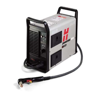
SPECIFICATIONS Dimensions and weight 10.5 in (267 mm) 23 in (584 mm) 90 lb (41 kg) 19.5 in AMP S (495 mm) Weight of the power supply without a torch powermax 1250 Operator Manual... -
Page 39: T80 Torches
SPECIFICATIONS T80 torches Handheld cutting capacity at 80 amps Recommended capacity 7/8 inch (22 mm) Maximum capacity 1-1/8 inch (29 mm) Severance capacity 1-1/2 inch (38 mm) Mechanized cutting capacity at 80 amps Recommended capacity 3/8 inch (10 mm) Maximum capacity 5/8 inch (16 mm) Gouging Capability 12.2 pounds (5.5 kg) hour... -
Page 40: Dimensions
SPECIFICATIONS Torch dimensions T80 dimensions 8.9" (226 mm) 1.5" (38 mm) 3.9" (99 mm) 2.25" (57 mm) 1.00" (25 mm) T80M dimensions 1.00" 15.25" (25 mm) (387 mm) 2.03" 8" 1.38" (52mm) (203 mm) (35 mm) 32 pitch 0.125" (3.2 mm) width 0.125"... -
Page 41: Symbols And Markings
The CE mark ( ) constitutes a manufacturer’s declaration of conformity to applicable European directives and standards. Only those versions of Hypertherm products with a CE mark located on or near the data plate have been tested for compliance with the European Low Voltage Directive and the European EMC Directive. -
Page 42: Setup
Section 3 SETUP n this section: Upon receipt ..........................3-2 Claims ............................3-2 Contents of box ........................3-2 Locating the power supply......................3-3 Lifting the power supply......................3-3 Power connection ........................3-4 Three-phase power cord – plug installation ................3-4 Single-phase power cord......................3-5 Power cord installation.....................3-5 Plug installation........................3-5 Grounding ..........................3-6 Extension cords ........................3-6 Torch installation........................3-7... -
Page 43: Upon Receipt
Claims for damage during shipment: If your unit was damaged during shipment, you must file a claim with the carrier. Hypertherm will furnish you with a copy of the bill of lading upon request. If you need additional assistance, call the nearest Hypertherm office listed in the front of this manual. -
Page 44: Locating The Power Supply
SETUP Locating the power supply Locate the Powermax1250 power supply with at least 10 inches (0.25 m) of open space at the front and back and fan side of the power supply for proper ventilation. Lifting the power supply WARNING •... -
Page 45: Power Connection
SETUP Power connection The Powermax1250 is a universal power supply that can configure itself to operate with AC voltages from 200 to 600 (230-400 3PH for CE model). Use a line disconnect switch for each power supply so that the operator can turn off the power supply quickly in an emergency. -
Page 46: Single-Phase Power Cord
SETUP Single-phase power cord (not for CE model) CAUTION: When using the standard model power supply (CE model is 3PH only) with a single-phase power source, replace the supplied power cord with a 6 AWG (16mm ) 3-wire power cord. The power cord must be connected by a licensed electrician. -
Page 47: Grounding
To ensure personal safety and proper operation, and to reduce electromagnetic interference (EMI), the Powermax1250 must be properly grounded through the power cord according to national or local electrical codes. Three-phase service must be of the 4-wire type with a green or green/yellow wire for protective earth ground and must comply with national or local electrical requirements. -
Page 48: Torch Installation
SETUP Torch installation Turn OFF power. Remove the power cord from the power receptacle. Open the ETR door and route the lead through the end cap. ETR door End cap powermax 1250 Operator Manual... - Page 49 SETUP Align the marks on the strain relief. Pull back the quick release collar and insert the lead’s gas fitting. Quick Release Collar Slide the quick release collar foward to lock in the gas fitting. Make sure that the gas fitting is secure.
-
Page 50: Plasma Gas Supply
SETUP Plasma gas supply The gas supply for the Powermax1250 can be shop compressed air or cylinder compressed air. A high-pressure regulator must be used on either type of supply and must be capable of delivering gas to the filter on the power supply at 400 scfh/6.7 scfm (189 l/min), minimum flow rate, at a minimum pressure of 90 psig (6.1 bar). -
Page 51: Gas Supply Installation
SETUP Gas supply installation Connect the air hose as follows: 1. Air fitting • Standard model: Install a 1/4 NPT gas fitting on the air filter inlet. CE model: Use a G1/4 adapter (supplied). Use liquid pipe sealant on threads. CAUTION: Never use Teflon tape when installing the nipple or adapters. -
Page 52: On/Off Pendant Connection
For the machine torch (T80M), inputs for arc start are available through the machine interface connection on the rear of the power supply. Plug the Hypertherm remote pendant (see Accessories in Section 5, Maintenance and parts , for part numbers) into the connector on the rear panel. -
Page 53: Arc Voltage
SETUP WARNING ELECTRIC SHOCK CAN KILL Disconnect electrical power before performing any maintenance. All work requiring removal of the power supply cover must be performed by a qualified technician. Arc voltage For systems other than the PowermaxEdge bundle, you can use arc voltage from the power supply to activate a torch height control. - Page 54 SETUP 4. Find the power board, as shown below. Use insulated type 1/4" faston terminal ends to connect to J15 and J16. Note: 120VAC or 24 VAC must be sourced externally. Signal: Arc voltage (torch height control) Type: Output Notes: Full arc voltage.
-
Page 55: Changing Xfer (Start Machine Motion) From Dry Contact Closure To Voltage Signal
SETUP Changing XFER (start machine motion) from dry contact closure to voltage signal 24 VDC (chassis ground reference) at 100ma max is available at J19 on the power board to drive an isolated/floating device such as a 24 VDC relay coil (240 ohms or greater) or a typical industrial input isolation module (which has an opto-coupler built-in). -
Page 56: Driving An Industrial Isolated Input Module
SETUP Driving an industrial isolated input module V-div - V-div + Start Signal Isolated input Shield module J16 J15 – XFER START Notes: • Customer-supplied isolated input module. • Pins 5 and 6 are used only on systems that include the PowermaxEdge cable with voltage divider. -
Page 57: Driving A Relay Coil With An External Power Source
SETUP Driving a relay coil with an external power source V-div - V-div + Start Signal 24 VDC Shield – J16 J15 XFER START Notes: • Customer-supplied 24 VDC relay coil > 240 ohms. • Customer-supplied 24 VDC power source. •... -
Page 58: Driving An Industrial Isolated Input Module With An External Power Source
SETUP Driving an industrial isolated input module with an external power source V-div - V-div + Start Signal 24 VDC – Shield Isolated input module J16 J15 XFER START – Notes: • Customer-supplied isolated input module. • Customer-supplied 24 VDC power source. •... -
Page 59: Powermax 1250 Operator Manual
SETUP powermax 1250 3-18 Operator Manual... - Page 60 Section 4 OPERATION In this section: Controls and indicators......................4-2 Indicator LEDs .........................4-2 T80 consumable configurations ....................4-3 Shielded...........................4-3 FineCut ..........................4-3 Gouging ...........................4-4 T80M consumable configurations ....................4-4 Shielded...........................4-4 FineCut ..........................4-5 Ohmic sensing retaining cap ...................4-5 Unshielded........................4-5 Install the torch consumables ....................4-7 Set the mode switch .........................4-8 Set the power switch to ON ......................4-8 Check the indicator lights ......................4-8 Adjust the gas pressure and current setting ................4-9...
- Page 61 OPERATION Cut charts ..........................4-15 80 amp mechanized shielded consumables..............4-15 60 amp mechanized shielded consumables..............4-16 40 amp mechanized shielded consumables..............4-17 FineCut consumables ....................4-18 40 amp mechanized unsheilded consumables..............4-19 powermax 1250 Operator Manual...
-
Page 62: Operation
OPERATION Controls and indicators ON (I) / OFF (0) switch Current Mode switch (Amps) AMPS adjustment knob Pressure gauge Indicator LEDs Pressure regulator Indicator LEDs Green power ON LED When illuminated, indicates that power is applied to system and power switch is ON ( I ). -
Page 63: T80 Consumable Configurations
OPERATION T80 consumable configurations Shielded O-ring 058519 120929 120928 120932 120926 120925 120929 120928 120931 120977 120928 120927 FineCut O-ring 30A — 50A 058519 220325* 220329 120926 220327** 120928 120979 *For use with CE systems. **The 22037 swirl ring is intended for manual cutting with FineCut consumables. -
Page 64: Gouging
OPERATION Gouging O-ring 058519 60A/80A 120977 120928 220059 120926 120925 T80M consumable configurations Shielded O-ring 058519 120930 120928 120932 120926 120925 120930 120928 120931 120927 120930 120928 powermax 1250 Operator Manual... -
Page 65: Finecut
OPERATION FineCut 30A – 50A O-ring 058519 220325* 120925 120926 220329 120928 120979 220061** 220404 Ohmic sensing retaining cap * In CE countries, unshielded consumables may only be used in mechanized torch applications. ** Use an ohmic sensing cap when a 220061** compatible torch height controller is installed. -
Page 66: Install The Torch Consumables
OPERATION Install the torch consumables WARNING INSTANT-ON TORCHES PLASMA ARC CAN CAUSE INJURY AND BURNS Plasma arc comes on immediately when the torch switch is activated. The plasma arc will quickly burn through gloves and skin. Make sure power is OFF before changing consumables. -
Page 67: Set The Mode Switch
OPERATION Set the mode switch Use to cut expanded metal. Automatically reinitiates pilot. Use to cut plate/sheet metal. Optimum consumable life. Use to gouge, or for non-transfered-arc operation. Set the power switch to ON Position the power switch to ON ( I ) as shown. Check the indicator lights Check that the POWER ON lamp is illuminated. -
Page 68: Adjust The Gas Pressure And Current Setting
OPERATION Adjust the gas pressure and current setting AMPS Set the current knob to gas test. Push the regulator knob to lock. AMPS Pull the regulator knob to unlock. Turn the current knob away from gas test to stop the gas flow (25 amps minimum). Set the pressure: Cutting 70–75 psig (4.8–5.2 bar) -
Page 69: Hand Torch Operation
OPERATION Hand torch operation WARNING INSTANT-ON TORCHES PLASMA ARC CAN CAUSE INJURY AND BURNS Plasma arc comes on immediately when the torch switch is activated. The plasma arc will quickly burn through gloves and skin. • Keep away from the torch tip. •... -
Page 70: Attach The Work Clamp
OPERATION WARNING SPARKS AND HOT METAL CAN INJURE EYES AND BURN SKIN When firing the torch at an angle, sparks and hot metal will spray out from the nozzle. Point the torch away from yourself and others. Attach the work clamp Attach the work clamp securely to the workpiece. -
Page 71: Hand Torch Cutting Technique
• To cut thin material, reduce the amps until you get the best quality cut. • For straight-line cuts, use a straight edge as a guide. To cut circles, use a template or a Hypertherm circle cut guide, part number 027668. powermax... -
Page 72: Piercing
OPERATION Piercing WARNING SPARKS AND HOT METAL CAN INJURE EYES AND BURN SKIN When firing the torch at an angle, sparks and hot metal will spray out from the nozzle. Point the torch away from yourself and others. Hold the torch so that the nozzle is within 1/8 inch (3 mm) from the workpiece before firing the torch. -
Page 73: Gouging
OPERATION Gouging WARNING SPARKS AND HOT METAL CAN INJURE EYES AND BURN SKIN When firing the torch at an angle, sparks and hot metal will spray out from the nozzle. Point the torch away from yourself and others. Hold the torch so that the nozzle is within 1/16 inch (1.5 mm) from the workpiece before firing the torch. -
Page 74: Cut Charts
OPERATION Cut charts 80 amp mechanized shielded consumables • Torch-to-work distance for the following cut chart is 1/16 inch (1.5 mm) for all cuts. Shield Retaining cap Nozzle Electrode Swirl ring T80M 120930 torch 120928 120927 120926 120925 Mild steel Material thickness Maximum travel speeds Optimum travel speeds... -
Page 75: 60 Amp Mechanized Shielded Consumables
OPERATION 60 amp mechanized shielded consumables • Torch-to-work distance for the following cut chart is 1/16 inch (1.5 mm) for all cuts. Shield Retaining cap Nozzle Electrode Swirl ring T80M 120930 torch 120928 120931 120926 120925 Mild steel Material thickness Maximum travel speeds Optimum travel speeds Pierce... - Page 76 OPERATION 40 amp mechanized shielded consumables • Torch-to-work distance for the following cut chart is 1/16 inch (1.5 mm) for all cuts. Shield Retaining cap Nozzle Electrode Swirl ring T80M 120930 torch 120928 120932 120926 120925 Mild steel Material thickness Maximum travel speeds Optimum travel speeds Pierce...
-
Page 77: Finecut Consumables
OPERATION FineCut consumables • Torch-to-work distance for the following cut chart is 0.08 inches (2 032 mm) for mild steel and 0.010 inches (0.254 mm) for stainless steel. Deflector Retaining Nozzle Electrode Swirl ring T80M torch 220325* 220329 120926 120925 120928 120979 * For use with CE systems. -
Page 78: 40 Amp Mechanized Unshielded Consumables
OPERATION 40 amp mechanized unshielded consumables • Torch-to-work distance for the following cut chart is 1/16 inch (1.5 mm) for all cuts. Deflector Retaining cap Nozzle Electrode Swirl ring T80M torch 120979 120928 220006 120926 120925 Mild steel Material thickness Maximum travel speeds Optimum travel speeds Pierce... - Page 79 OPERATION powermax 1250 4-20 Operator Manual...
-
Page 80: Maintenance And Parts
Section 5 MAINTENANCE AND PARTS In this section: Routine maintenance .......................5-2 Inspect the consumables......................5-3 Controls and indicators......................5-4 Indicator LEDs .........................5-4 Basic troubleshooting .......................5-5 System circuit diagram ......................5-8 Technical questions ........................5-9 Parts ............................5-9 Torch parts ........................5-9 Power supply parts ......................5-10 Accessories ........................5-10 powermax 1250 Operator Manual... -
Page 81: Routine Maintenance
MAINTENANCE AND PARTS Routine maintenance WARNING ELECTRIC SHOCK CAN KILL Disconnect electrical power before performing any maintenance. All work requiring removal of the power supply cover must be performed by a qualified technician. Each Use Check consumables for Check gas pressure. wear and proper installation. -
Page 82: Inspect The Consumables
Damage or debris Replace Central bore (I.D.) Does electrode slide easily? Replace Gas holes Blocked holes Replace Torch o-ring External surfaces Damage or wear Replace Dry surface Apply a thin film of Hypertherm grease (part number 027055). powermax 1250 Operator Manual... -
Page 83: Controls And Indicators
MAINTENANCE AND PARTS Controls and indicators ON (I) / OFF (0) switch Current Mode switch (amps) AMPS adjustment knob Pressure gauge Indicator LEDs Pressure regulator Indicator LEDs Green power ON LED When illuminated, indicates that power is applied to system and power switch is ON ( I ). -
Page 84: Basic Troubleshooting
MAINTENANCE AND PARTS Basic troubleshooting Problem Cause / Solution 1. The ON/OFF power switch is set to 1.1 The power cord is not plugged into the ON ( I ), and the power ON (green) power receptacle. LED is not illuminated. Plug the power cord into the receptacle. - Page 85 MAINTENANCE AND PARTS Basic troubleshooting (continued) Problem Cause / Solution The power ON (green), torch cap .1 Retaining cap is loose or removed from (yellow) and fault (red) LEDs are the torch. illuminated. Turn off power supply and tighten or install torch consumables.
- Page 86 MAINTENANCE AND PARTS Basic troubleshooting (continued) Problem Cause / Solution 8. The arc sputters and hisses. .1 The gas filter element outside the power supply is contaminated. Replace filter element. 8.2 There is water in the air line. Clean air filter or add additional air filtration to power supply.
-
Page 87: System Circuit Diagram
MAINTENANCE AND PARTS System circuit diagram powermax 1250 Operator Manual... -
Page 88: Technical Questions
If you are unable to fix the problem by following this basic troubleshooting guide or if you need further assistance: 1. Call your Hypertherm distributor or authorized Hypertherm repair facility. 2. Call the nearest Hypertherm Technical Service team listed in the front of this manual. Parts Torch parts See Section 4, T80 consumable configurations and T80M consumable configurations , for part numbers and illustrations of the consumables. -
Page 89: Power Supply Parts
ETR door assembly 128387 Consumables box 123106 Work clamp with cable and strain relief 128666 Kit: Powermax1000/1250 power cord, standard 128667 Kit: Powermax1250 power cord, CE 128631 Kit: Powermax1250 labels 128632 Kit: Powermax1250 labesl, CE 128672 ON/OFF switch Accessories 128646...
Need help?
Do you have a question about the POWERMAX1250 and is the answer not in the manual?
Questions and answers