
Related Manuals for Hypertherm powermax1000


Summary of Contents for Hypertherm powermax1000
- Page 1 ® Plasma Arc Cutting System Service Manual 804300 Revision 0 AMPS...
-
Page 2: Service Manual
Service Manual (P/N 804300) Revision 0 December, 2001 Hypertherm, Inc. Hanover, NH USA www.hypertherm.com © Copyright 2001 Hypertherm, Inc. All Rights Reserved Hypertherm and Powermax are trademarks of Hypertherm, Inc. and may be registered in the United States and/or other countries. - Page 3 63457 Hanau-Wolfgang, Deutschland 49 6181 58 2100 Tel 49 6181 58 2134 Fax 49 6181 58 2123 (Technical Service) Hypertherm (S) Pte Ltd No. 19 Kaki Bukit Road 2 K.B. Warehouse Complex Singapore 417847, Republic of Singapore 65 6 841 2489 Tel...
-
Page 4: Hypertherm Plasma Systems
The size of the surrounding area to be Earthing of Workpiece considered will depend on the structure of Hypertherm's CE-marked equipment is built Where the workpiece is not bonded to earth the building and other activities that are tak- in compliance with standard EN50199. The for electrical safety, nor connected to earth ing place. -
Page 5: Warranty
Hypertherm system. Any damage infringement, and Hypertherm’s obligation to indemnify shall be caused by the use of other than genuine Hypertherm parts may conditioned upon Hypertherm’s sole control of, and the not be covered by the Hypertherm warranty. -
Page 6: Table Of Contents
Sécurité des bouteilles de gaz comprimé .......................1a-5 Les bouteilles de gaz comprimé peuvent exploser en cas de dommages .............1a-5 Le bruit peut provoquer des problèmes auditifs......................1a-5 Pacemakers et prothèses auditives ........................1a-5 Un arc plasma peut endommager les tuyaux gelés....................1a-5 Étiquette de sécurité ...............................1a-6 powermax1000 Service Manual... - Page 7 Heat Sink Assembly ..............................4-6 Recommended Spare Parts .............................4-7 Section 5 Parts List – Torch and Consumables T60 Hand Torch Assembly ............................5-2 T60M Machine Torch Assembly ..........................5-4 Torch Consumable Configurations..........................5-6 Recommended Spare Parts .............................5-7 Section 6 Wiring Diagrams Electrical Schematic ..............................6-2 powermax1000 Service Manual...
-
Page 8: Safety
Grounding Safety ............................1-4 Compressed Gas Equipment Safety.......................1-5 Gas Cylinders Can Explode If Damaged ......................1-5 Noise Can Damage Hearing ...........................1-5 Pacemaker and Hearing Aid Operation......................1-5 A Plasma Arc Can Damage Frozen Pipes ......................1-5 Additional Safety Information ..........................1-5 Warning Label ..............................1-6 Hypertherm Plasma Systems... -
Page 9: Recognize Safety Information
• Install an aeration manifold on the floor of the water closed container. table to eliminate the possibility of hydrogen • Do not cut containers that have held combustible detonation. Refer to the Appendix section of this materials. manual for aeration manifold details. Hypertherm Plasma Systems 11-98... -
Page 10: Electric Shock Can Kill
• Provide a disconnect switch close to the power grounding conductor first. supply with properly sized fuses. This switch allows • Each Hypertherm plasma system is designed to be the operator to turn off the power supply quickly in used only with specific Hypertherm torches. Do not an emergency situation. -
Page 11: A Plasma Arc Can Cause Injury And Burns
Work Table Connect the work table to an earth power cord ground. Fasten the retaining nut tightly. ground, in accordance with appropriate national or • Tighten all electrical connections to avoid excessive local electrical codes. heating. Hypertherm Plasma Systems 4-99... -
Page 12: Compressed Gas Equipment Safety
Protection Association, 470 Atlantic Avenue, Boston, MA 02210 Hazardous Substances, American Welding Society 10. OSHA, Safety and Health Standards, 29FR 1910 550 LeJeune Road, P.O. Box 351040, Miami, FL 33135 U.S. Government Printing Office, Washington, D.C. 20402 Hypertherm Plasma Systems 11-98... -
Page 13: Warning Label
Wear complete body protection. Become trained and read the instructions before working on the machine or cutting. Do not remove or paint over (cover) warning labels. 110391 Rev A Hypertherm Plasma Systems 8-99... -
Page 14: Sécurité
Les bouteilles de gaz comprimé peuvent exploser en cas de dommages............1-5 Le bruit peut provoquer des problèmes auditifs ....................1-5 Pacemakers et prothèses auditives ........................1-5 Un arc plasma peut endommager les tuyaux gelés ..................1-5 Étiquette de sécurité ............................1-6 Hypertherm Systèmes plasma 1a-1 2/12/01... -
Page 15: Identifier Les Consignes De Sécurité
• Ne pas couper de récipients contenant des matières Se référer à l’annexe du manuel pour plus de combustibles. renseignements sur les collecteurs d’aération. 1a-2 Hypertherm Systèmes plasma 2/12/01... -
Page 16: Les Chocs Électriques Peuvent Être Fatals
• Installer un sectionneur avec fusibles appropriés, à la prise de terre appropriée. proximité de la source de courant. Ce dispositif permet à • Chaque système plasma Hypertherm est conçu pour être l’opérateur d’arrêter rapidement la source de courant en utilisé uniquement avec des torches Hypertherm cas d’urgence. -
Page 17: L'arc Plasma Peut Provoquer Des Blessures Ou Des Brûlures
Bien serrer l’écrou de retenue. Table de travail Raccorder la table de travail à la terre, • S’assurer que toutes les connexions sont bien serrées conformément aux codes de sécurité locaux ou nationaux pour éviter la surchauffe. appropriés. 1a-4 Hypertherm Systèmes plasma 2/12/01... -
Page 18: Sécurité Des Bouteilles De Gaz Comprimé
LES TUYAUX GELÉS • Se tenir le plus loin possible de la source de courant. Les tuyaux gelés peuvent être endommagés ou éclater si l'on essaie de les dégeler avec une torche plasma. Hypertherm Systèmes plasma 1a-5 2/12/01... -
Page 19: Étiquette De Sécurité
6. Se former à la technique du coupage et lire les instructions avant de manipuler l’équipement ou de procéder au coupage. 7. Ne pas retirer ou peindre (recouvrir) les étiquettes de sécurité. 1a-6 Hypertherm Systèmes plasma 2/12/01... - Page 20 Section 2 SPECIFICATIONS In this section: Specifications – Power Supply ..........................2-2 Power Supply – Dimensions and Weight ......................2-3 Specifications – T60 Torches ............................2-4 Torch Dimensions ..............................2-5 Symbols and Markings .............................2-6 powermax1000 Service Manual...
-
Page 21: Specifications
Drooping *Defined as a plot of output voltage versus output current Rated Output Current (I 20A – 60A Hypertherm Standard Rated Output 140 VDC Voltage (U Duty Cycle (X*) at 104°F (40°C) at – Volts AC rms rated conditions (U... -
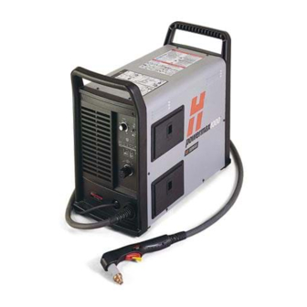
Page 22: Power Supply - Dimensions And Weight
SPECIFICATIONS Power Supply – Dimensions and Weight 76 lb (34.5 kg) 10.5 in (267 mm) 23 in (584 mm) Weight of power supply without torch 19.5 in (495 mm) AMP S powermax1000 Service Manual... -
Page 23: Specifications - T60 Torches
4.5 pounds (2.0 kg) with 15 ft (4.5 m) lead T60M 8.3 pounds (3.8 kg) with 25 ft (7.5 m) lead 9.9 pounds (4.5 kg) with 35 ft (10.7 m) lead 15.0 pounds (6.8 kg) with 50 ft (15 m) lead powermax1000 Service Manual... -
Page 24: Torch Dimensions
8.9" (226 mm) 1.5" (38 mm) 3.9" (99 mm) 2.25" (57 mm) 1.00" (25 mm) T60M Machine Torch Dimensions 15.06" (383 mm) 1.38" 1.00" (35 mm) (25 mm) 1.13" 8" (29mm) (203 mm) 32 pitch .125" (3.2 mm) width powermax1000 Service Manual... -
Page 25: Symbols And Markings
Plasma torch in the TEST position (cooling and cutting gas exiting nozzle) Plasma torch cutting and gouging Power is on AC input power connection Power is off The terminal for the external Volt/amp curve, "drooping" protective (earth) conductor characteristic powermax1000 Service Manual... - Page 26 Visual Inspection – External ..........................3-5 Visual Inspection – Internal ..........................3-6 Resistance Checks ..............................3-7 Troubleshooting Guide..............................3-9 Voltage Checks...............................3-13 Component Replacement ............................3-18 Power Cord Replacement ..........................3-18 Torch Installataion ............................3-19 Filter Element Replacement...........................3-21 Work Cable Replacement ..........................3-22 Capacitor Replacement..........................3-23 Heat Sink Component Replacement......................3-24 powermax1000 Service Manual...
-
Page 27: Controls And Indicators
When illuminated, indicates that a fault condition exists, which prevents system operation. Yellow Low Line Voltage LED When illuminated, indicates that line voltage is below 170 VAC or above 680 VAC. On CE units, it can also indicate a missing phase. powermax1000 Service Manual... -
Page 28: Theory Of Operation
The control board PCB3 includes a pilot arc control switch, allowing the operator to turn the pilot arc ON (useful when cutting expanded metal), OFF (for maximum life of consumables), or increase the pilot arc to 20A (useful for gouging or non-transferred-arc cutting). powermax1000 Service Manual... -
Page 29: Sequence Of Operation
• Position torch on work piece. • Select desired cutting amps • Depress plasma start switch on hand torch or with current adjustment knob. remote start switch for machine torch. Gas solenoid valve V1 closes. Power circuits are ready. Gas flow stops. powermax1000 Service Manual... -
Page 30: Troubleshooting
The complexity of the circuits requires that service technicians have a working knowledge of inverter power supply theory. In addition to being technically qualified, technicians must perform all testing with safety in mind. If questions or problems arise during servicing, call the nearest Hypertherm Technical Services Department listed in the front of this manual. -
Page 31: Visual Inspection - Internal
2. Remove the cover of the power supply by removing the 12 securing screws. 3. Inspect the inside of the power supply, especially on the side with the power board. Look for broken or loose wiring connections, burn and char marks, damaged components, etc. Repair or replace as necessary. powermax1000 Service Manual... -
Page 32: Resistance Checks
Resistance Check #1 1. With the power disconnected, set the ON/OFF switch S1 to ON. 2. Check resistance across input leads. 3. Check resistance from input leads to ground. 2.4 MΩ 2.4 MΩ 2.4 MΩ >20 MΩ powermax1000 Service Manual... - Page 33 MAINTENANCE Resistance Check #2 • Check resistance across output diode bridge. 50 KΩ 40 K 10 K 40 K 10 K 50 KΩ powermax1000 Service Manual...
-
Page 34: Troubleshooting Guide
The Troubleshooting Guide provides most probable causes and solutions. Study the system wiring diagram and understand the theory of operation before troubleshooting. Before purchasing a major replacement component, verify the problem with Hypertherm Technical Service or the nearest Hypertherm repair facility. powermax1000... - Page 35 Problem This May Mean Cause Solution Turn power switch ON and Insufficient voltage to No voltage or improper voltage Verify incoming voltage is between 200-600 VAC. Power On LED does not control circuits or shorted applied to unit illuminate power component Defective power switch (S1) Measure AC voltage at bottom terminals of switch.
- Page 36 Problem This May Mean Cause Solution Yellow cap sensing LED Safety circuit not satisfied Consumables not installed, Refer to consumable diagram for proper installation. Try illuminates installed improperly, or new consumables. damaged Damage to safety circuit Remove torch. Check torch end of connector. Install consumables and check continuity on J18, pins 11 and 12 orange and blue wires.
- Page 37 Problem This May Mean Cause Solution When pressing torch Worn consumables Worn-out consumables Replace consumables trigger/start switch, pilot arc Improper air pressure Insufficient supply or air leak on Turn current adjust knob to test flow and set pressure starts but “pops out” before setting or low flow supply line regulator to 70 psi (4.7 bar) for cutting or 50 psi (3.4...
-
Page 38: Voltage Checks
• This voltage check only applies to 3-phase. • Check input voltage to the input diode bridge. • The AC voltage between any 2 input wires should equal the line voltage. = Line Voltage* = Line Voltage = Line Voltage* powermax1000 Service Manual 3-13... - Page 39 MAINTENANCE Voltage Check #2 • Check output voltage of the input diode bridge. • Output VDC = Line Voltage * 1.414 Line Voltage * 1.414 powermax1000 3-14 Service Manual...
- Page 40 MAINTENANCE Voltage Check #3 • Check voltage across IGBT module (Q7). 750 VDC powermax1000 Service Manual 3-15...
- Page 41 MAINTENANCE Voltage Check #4 • Check voltage across IGBT module (Q6). 750 VDC 375 VDC 375 VDC powermax1000 3-16 Service Manual...
- Page 42 MAINTENANCE Voltage Check #5 • Check voltage across power supply capacitors. 375 VDC powermax1000 Service Manual 3-17...
-
Page 43: Component Replacement
2. Install the power cord connections where shown. 3. Tighten the strain relief onto the power cord. 4. Install the power supply cover. 5. Reconnect electrical power and gas supply. Black White Black White Green Green Single Phase Three Phase powermax1000 3-18 Service Manual... -
Page 44: Torch Installataion
MAINTENANCE Torch Installation Turn power OFF. Remove power cord from power receptacle. Open ETR door and route the lead through the end cap. Door End Cap powermax1000 Service Manual 3-19... - Page 45 Slide quick-release collar foward to lock in the gas fitting. Make sure that the gas fitting is secure. Make sure that the red dot on the connector is on top, then plug in the electrical connector. Close ETR door. powermax1000 3-20 Service Manual...
-
Page 46: Filter Element Replacement
NOTE: Do not allow the filter element to turn when loosening the screw. Install filter bowl. A. Slide filter bowl over filter element. B. Align marks on filter bowl and filter body. C. Rotate filter bowl until it locks in place. powermax1000 Service Manual 3-21... -
Page 47: Work Cable Replacement
Tighten nut to 10 in-lb (12 kg cm) of torque. 4. Install ETR barrier 5. Install the power supply cover. CAUTION: This is a high-current connection. Proper torque is critical. Connect to J14 Strain Relief Barrier Work Cable powermax1000 3-22 Service Manual... -
Page 48: Capacitor Replacement
Install new capacitor and secure with 2 screws. Tighten screws to 20 inch pounds (24 kg cm). Install the power supply cover. Remove and install screws from power board side. Remove and install Correct Installation capacitors from fan side. powermax1000 Service Manual 3-23... -
Page 49: Heat Sink Component Replacement
Thermal Pad Notes: Apply thermal grease and torque to 8 in-lb (9 kg cm.) Apply thermal grease and torque to 20 in-lb (23 kg cm). Apply thermal grease and torque to 35 in-lb (40 kg cm). powermax1000 3-24 Service Manual... -
Page 50: Parts - Power Supply
Section 4 PARTS - POWER SUPPLY In this section: Exterior ..................................4-2 Interior Right Side ..............................4-3 Back Interior Right side.............................4-4 Interior Fan Side ...............................4-5 Heat Sink Assembly ..............................4-6 Recommended Spare Parts .............................4-7 powermax1000 Service Manual... -
Page 51: Exterior
Front end panel, CE 008965 Current adjustment knob 128630 End cap screws 123645 Ground clamp 011096 Regulator knob 128629 Cover screws 128690 Power supply cover with labels, Domestic 128688 Power supply cover with labels, CE 128626 Rear end panel powermax1000 Service Manual... -
Page 52: Interior Right Side
Pressure Regulator 128699 Pilot Arc IGBT Gate Drive Cable 128622 Gas Manifold 128628 ETR Box 046116 Tubing, 8mm OD, 6mm ID, nylon 3 ft. 108211 On/Off Knob 128662 Machine interface 128695 Power PCB PCB2 123602 Gate Drive Cables powermax1000 Service Manual... -
Page 53: Back Interior Right Side
AM PS PS I BA R Part Item Number Description Designator Qty. 128665 Strain relief, arc voltage 128672 Power switch 128706 EMI Filter PCB, CE only PCB1 128666 Power cable, Domestic 3PH 128705 Power cable, CE 3PH powermax1000 Service Manual... -
Page 54: Interior Fan Side
Power Supply – Interior Fan Side Part Item Number Description Designator Qty. 128627 Filter bowl 011093 Air filter element 011094 O-ring 128707 Fan subassembly 128693 Inductor, input choke 128691 Capacitor 128692 Power transformer 128694 Inductor, output choke powermax1000 Service Manual... -
Page 55: Heat Sink Assembly
Thermal grease, 5 oz. DC-340 128677 Output diode bridge 128697 IGBT, inverter 128700 Temperature Switch PCB4 128708 IGBT, PFC 128696 Input diode bridge 128670 Snubber resister 128699 IGBT, pilot arc 128669 Snubber resister Reference page 3-24 for torque specifications. powermax1000 Service Manual... -
Page 56: Recommended Spare Parts
PARTS - POWER SUPPLY Recommended Spare Parts – Powermax1000 Part Number ........Description....................Page Reference 128689..........Front end panel, Domestic................4-2 128687..........Front end panel, CE..................4-2 128626..........Rear end panel ....................4-2 008965..........Current adjustment knob ..................4-2 128686..........Labels, Domestic .....................4-2 128685..........Labels, CE ......................4-2 128690..........Power supply cover, Domestic .................4-2 128688..........Power supply cover, CE ...................4-2... - Page 57 PARTS - POWER SUPPLY powermax1000 Service Manual...
-
Page 58: Parts List - Torch And Consumables
Section 5 PARTS LIST - TORCH AND CONSUMABLES In this section: T60 Hand Torch Assembly ............................5-2 T60M Machine Torch Assembly ..........................5-4 Torch Consumable Configurations..........................5-6 Recommended Spare Parts .............................5-7 powermax1000 Service Manual... -
Page 59: T60 Hand Torch Assembly
ETR Repair Kit (Regional Repair Centers only) 128642 Start Switch * Top assembly includes the following consumables (See page 4-3 for details of consumable parts): 120926 Electrode 120925 Swirl Ring 120928 Retaining Cap 120929 Shield 120931 Nozzle powermax1000 Service Manual... - Page 60 PARTS – TORCH AND CONSUMABLES powermax1000 Service Manual...
-
Page 61: T60M Machine Torch Assembly
ETR Repair Kit (Regional Repair Centers only) 128645 Torch Mounting Kit (for reassembly after installation) * Top assembly includes the following consumables (See page 4-3 for details of consumable parts): 120926 Electrode 120925 Swirl Ring 120928 Retaining Cap 120929 Shield 120931 Nozzle powermax1000 Service Manual... - Page 62 PARTS – TORCH AND CONSUMABLES powermax1000 Service Manual...
-
Page 63: Torch Consumable Configurations
Gouging 120977 120928 220059 Unshielded* 120979 120928 220006 O-Ring 058519 120979 120928 220007 120926 120925 Mechanized, Shielded 120930 120928 120932 * In CE countries, unshielded consumables may only be used in mechanized torch applications. 120930 120928 120931 powermax1000 Service Manual... -
Page 64: Recommended Spare Parts
T60M/T80M Machine Torch Replacement Lead 25 ft (7.6 m) 128635 T60M/T80M Machine Torch Replacement Lead 35 ft (10.7 m) 128641 T60M/T80M Machine Torch Replacement Lead 50 ft (15.2 m) 128643 T60M/T80M Mounting Sleeve Replacement Kit 128645 T60M/T80M Mounting Kit powermax1000 Service Manual... - Page 65 PARTS – TORCH AND CONSUMABLES powermax1000 Service Manual...
-
Page 66: Wiring Diagrams
Section 6 WIRING DIAGRAMS In this section: Electrical Schematic ..............................6-2 powermax1000 Service Manual... - Page 67 PROPRIETARY AND MAY NOT BE USED ANGULAR ±.5∞ FOR MANUFACTURING OR FABRICATION PART MUST BE FREE OF BURRS AND SHARP DRAWN BY DATE APPROVED BY DATE PURPOSES WITHOUT PERMISSION EDGES. BREAK SHARP EDGES IF NECESSARY FROM HYPERTHERM, INC. 5-11-01 WITH CHAMFER OR RADIUS .015 MAX.
Need help?
Do you have a question about the powermax1000 and is the answer not in the manual?
Questions and answers