MTS Systems Level Plus Operation And Installation Manual
M-series model mr analog transmitter
Hide thumbs
Also See for Level Plus:
- Interface manual (12 pages) ,
- Operation and installation manual (115 pages)

Related Manuals for MTS Systems Level Plus


Summary of Contents for MTS Systems Level Plus
- Page 1 Level Plus ® Magnetostrictive Liquid-Level Transmitters with Temposonics Technology ® OPERATION AND INSTALLATION MANUAL M-Series Model MR Analog Transmitter The Measurable Difference...
-
Page 3: Contact Information
Monday - Thursday: 8:00 a.m. to 5:00 p.m. Fax: +1-919-677-2343 Friday: 8:00 a.m. to 4:00 p.m. E-mail: info.us@mtssensors.com REMITTANCE ADDRESS: http://www.mtssensors.com MTS Systems Corporation MAILING AND SHIPPING ADDRESS: Sensors Division MTS Systems Corporation NW 5872 Sensors Division P.O. Box 1450... -
Page 4: Reference Information
“Introduction”, provides an overview of the manual. “Terms and Definitions”, provides definitions of terms used in this manual. “Product Overview”, gives an overall product description for the Level Plus liquid-level transmitter, its specifications, use, output, and electronics. “Installation and Mounting”, provides detailed installation and mounting information. -
Page 5: Table Of Contents
Recommended cable types ........... 16 Cable specifications ..............16 Electrical conduit installation ........16 Grounding ............... 17 Level Plus ® Liquid-Level Transmitters M-Series Model MR Analog Transmitter MTS Sensors Operation and Installation Manual, Document Number: 550720 Revision K (EN) 02/2016... - Page 6 Level Plus Liquid-Level Transmitters M-Series Model MR Analog Transmitter ® Operation and Installation Manual, Document Number: 550720 Revision K (EN) 02/2016 MTS Sensors...
-
Page 7: Introduction
Model MR Operation and Installation Manual Introduction Introduction MTS is recognized as the pioneer, innovator and leader in magnetostrictive sensing. The new Level Plus M-Series transmitter design repre- ® sents a continuation of our on-going effort to provide effective, innovative and reliable products to the Liquid Level marketplace. -
Page 8: Terms And Definitions Reference
Specific Gravity – The density ratio of a liquid to the density of water at the same conditions. Level Plus ® Liquid-Level Transmitters - M-Series Model MR Analog Transmitter Operation and Installation Manual, Part No.: 550720 Revision K (EN) 02/2016... -
Page 9: Model Mr Product Overview
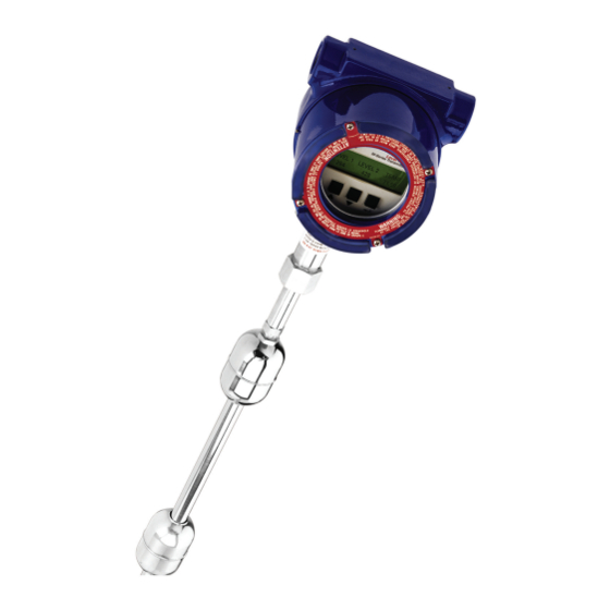
„ AMS Aware Components The Level Plus Model MR liquid level transmitter consists of four main components; a housing, outer pipe, float, and electronics. Varying the components of the transmitter allows the transmitter to be customized to almost any application. -
Page 10: Outer Pipe Configurations
Bottom-fixing Hook Bottom-fixing Bottom-fixing Weight Magnet Figure 3. 7/8 in. diameter flexible pipe of 316L stainless steel Level Plus ® Liquid-Level Transmitters - M-Series Model MR Analog Transmitter Operation and Installation Manual, Part No.: 550720 Revision K (EN) 02/2016 MTS Sensors... -
Page 11: Floats
(RTD) mounted inside the transmitter’s outer pipe assembly. The RTD is a 1000 ohm platinum film device. ACCESSORIES MTS also offers a series of displays, housings, converters, and other accessories, please refer to the ‘Accessories Catalog’, MTS part number 551103. Level Plus ® Liquid-Level Transmitters - M-Series Model MR Analog Transmitter MTS Sensors... -
Page 12: Theory Of Operation
A Material Safety Data Sheet (MSDS) must also accompany the Material Authorization (RMA) information if required. transmitter that was used in any process. Level Plus ® Liquid-Level Transmitters - M-Series Model MR Analog Transmitter Operation and Installation Manual, Part No.: 550720 Revision K (EN) 02/2016... -
Page 13: Model Number Identification
7620 mm (300 in.) SPECIAL Standard product Engineering special (not affecting agency controlled parts or features) Level Plus ® Liquid-Level Transmitters - M-Series Model MR Analog Transmitter MTS Sensors Operation and Installation Manual, Part No.: 550720 Revision I (EN) 06/2014... - Page 14 Metric (millimeters) Encode length in millimeters if using metric US Customary (inches) Encode length in inches if ordering (XXXXX mm) in US Customary (XXX.XX in.) Level Plus ® Liquid-Level Transmitters - M-Series Model MR Analog Transmitter Operation and Installation Manual, Part No.: 550720 Revision K (EN) 02/2016...
- Page 15 Flexible transmitter: 3048 mm (120 in.) to 12,192 mm (480 in.) except ATEX, Ex ia IIB max. length 7620 mm (300 in.) SPECIAL Standard product Engineering special (not affecting agency controlled parts or features) Level Plus ® Liquid-Level Transmitters - M-Series Model MR Analog Transmitter MTS Sensors...
-
Page 16: Atex/Iecex
Full scale to 152 mm (6 in.) from zero range: Size: 13 mm (0.5 in.) Number of digits: Level Plus ® Liquid-Level Transmitters - M-Series Model MR Analog Transmitter Operation and Installation Manual, Part No.: 550720 Revision K (EN) 02/2016 MTS Sensors... -
Page 17: Installation And Mounting
Stilling wells and guide poles Level Plus transmitters can be mounted in slotted or unslotted stilling wells but a slotted stilling well is always preferred. Using a unslotted stilling well will negatively affect performance of any level device as the level in the stilling well can differ from the level in the tank. The Level Plus transmitter can also be installed to one side of the stilling well to also allow for sampling and manual gauging from the same opening as the automatic tank gauging. -
Page 18: Flexible Probe
Tighten the adjustable fitting to hold the transmitter in place. 7. Terminate the field wire cables noting proper wire orientation. Level Plus ® Liquid-Level Transmitters - M-Series Model MR Analog Transmitter Operation and Installation Manual, Part No.: 550720 Revision K (EN) 02/2016... -
Page 19: Mounting
Interface float Bottom-fixing weight, magnet or hook Figure 7. Welded flange mounting for rigid and flexible pipe Level Plus ® Liquid-Level Transmitters - M-Series Model MR Analog Transmitter MTS Sensors Operation and Installation Manual, Part No.: 550720 Revision K (EN) 02/2016... -
Page 20: Sanitary Tri-Clamp Mounting
This end plug style has permanently mounted floats. Floats cannot be removed from pipe. Figure 9. End-plug options for transmitters in a sanitary pipe application Level Plus ® Liquid-Level Transmitters - M-Series Model MR Analog Transmitter Operation and Installation Manual, Part No.: 550720 Revision K (EN) 02/2016... -
Page 21: Electrical Connections And Wiring Procedures
Electrical connections and wiring procedures A typical intrinsically safe connection for the Level Plus Model MR transmitter includes protective safety barriers, a power supply and a reading or monitoring device. Refer to Agency information and Brief Operation Manual for Safe Use for detailed information. -
Page 22: Recommended Cable Types
Model MR Operation and Installation Manual Cable Types and Electrical Conduit Installation Recommended cable types Refer to ‘Table 1’ below for general requirements of cable types for the Level Plus Model MR analog transmitter. CABLE SPECIFICATIONS Parameter Specification Minimum cable size 24 AWG or heavier (0.51 mm diameter) -
Page 23: Grounding
24 Vdc Supply- Transmitter Voltage I (A) 4-20 I.S. Ground connection Figure 12. Safety barrier connections Level Plus ® Liquid-Level Transmitters - M-Series Model MR Analog Transmitter MTS Sensors Operation and Installation Manual, Part No.: 550720 Revision K (EN) 02/2016... -
Page 24: Maintenance And Field Service
FLOAT MAINTENANCE Level Plus M-Series transmitters use magnetostrictive technology and only have one moving part—the float. This technology ensures no scheduled maintenance or recalibration is required. However, MTS recommends that you check the transmitter pipe annually for build up of process material. -
Page 25: Setup
Loop 2 Test + — + — operation. You can use these modes to calibrate and set up various operating parameters. Level Plus ® Run Mode M-Series Transmitter Run mode is the primary mode of operation. This mode will perform Custom LCD Display measurements, display data, and respond to HART commands. -
Page 26: Lcd Display And Keypad (Optional)
MANUAL CALIBRATION The procedure to enter calibration mode and modify levels 1 and 2, adjust LCD contrast and perform a LCD testis shown in Figure 15 on the next page. Level Plus ® Liquid-Level Transmitters - M-Series Model MR Analog Transmitter Operation and Installation Manual, Part No.: 550720 Revision K (EN) 02/2016... - Page 27 Tests all segments Perform of LCD LCD Test? (lasts 10 seconds) Figure 15. Manual calibration matrix Level Plus ® Liquid-Level Transmitters - M-Series Model MR Analog Transmitter MTS Sensors Operation and Installation Manual, Part No.: 550720 Revision K (EN) 02/2016...
-
Page 28: Setup Using Hart Field Communicator
3. Follow safe working procedures for working on live equipment in a hazardous location before you remove the housing cover. 4. Connect the HART Field Communicator to the terminals that are labeled HART located on the front panel display of the Level Plus transmitter. -
Page 29: Setup Using Mts Field Setup Software
250 ohm load resistor may need to be added to the loop for HART to communicate effectively. 3. Turn on power 4. Open Setup Software. Data should fill in. If no data appears select a different serial communication port. Level Plus ® Liquid-Level Transmitters - M-Series Model MR Analog Transmitter MTS Sensors Operation and Installation Manual, Part No.: 550720 Revision K (EN) 02/2016... -
Page 30: Advanced Setup Tab
Display: The optional LCD display that can be enabled or disabled Alarm: The output state that the level transmitter enters upon failure. Alarm can be Low (3.8 mA) or High (21.5 mA). Level Plus ® Liquid-Level Transmitters - M-Series Model MR Analog Transmitter Operation and Installation Manual, Part No.: 550720 Revision K (EN) 02/2016... -
Page 31: Calibration Tab
(Advance Setup or Calibration). Read: This button sends a single read command to the transmitter and displays the data which the transmitter responds with. Level Plus ®... -
Page 32: Agency Information
Ex d IIB T4 Ga/Gb IEC 60079-1:2007-04 Ta = -20° C to 40° C IEC 60079-26:2006 Level Plus ® Liquid-Level Transmitters - M-Series Model MR Analog Transmitter Operation and Installation Manual, Part No.: 550720 Revision K (EN) 02/2016 MTS Sensors... - Page 33 ABNT NBR IEC 60079-26:2008 Ta = -20° C to 40° C Portaria INMETRO no 179 de 18/05/2010 Level Plus ® Liquid-Level Transmitters - M-Series Model MR Analog Transmitter MTS Sensors Operation and Installation Manual, Part No.: 550720 Revision K (EN) 02/2016...
-
Page 34: Hazardous Area Installation
Model MR Operation and Installation Manual Agency Information, CSA Hazardous area installation Figure 16. CSA installation drawing (Reference only, see 650805) Level Plus ® Liquid-Level Transmitters - M-Series Model MR Analog Transmitter Operation and Installation Manual, Part No.: 550720 Revision K (EN) 02/2016... -
Page 35: Installation Drawings
Model MR Operation and Installation Manual Agency Information, CSA INSTALLATION DRAWING (FIGURE 17) Figure 17. CSA installation drawing (Reference only, see 650805) Level Plus ® Liquid-Level Transmitters - M-Series Model MR Analog Transmitter MTS Sensors Operation and Installation Manual, Part No.: 550720 Revision K (EN) 02/2016... -
Page 36: Notes
Class II, Division 1, Groups E, F, G Class III, Type 4X Table 4. CSA model number approval classification Level Plus ® Liquid-Level Transmitters - M-Series Model MR Analog Transmitter Operation and Installation Manual, Part No.: 550720 Revision K (EN) 02/2016... -
Page 37: Wiring And Connections
Loop 2 (-) Loop 2 (+) Not used Not used Figure 19. NEMA 4X housing with 6-pin connection Level Plus ® Liquid-Level Transmitters - M-Series Model MR Analog Transmitter MTS Sensors Operation and Installation Manual, Part No.: 550720 Revision K (EN) 02/2016... - Page 38 Loop 1 (+) Loop 2 (+) Loop 1 (–) Loop 2 (–) Figure 21. Single-cavity housing Level Plus ® Liquid-Level Transmitters - M-Series Model MR Analog Transmitter Operation and Installation Manual, Part No.: 550720 Revision K (EN) 02/2016 MTS Sensors...
- Page 39 Loop 1 (–) Loop 2 (–) Loop 1 (+) Loop 2 (+) Earth Ground Figure 22. Dual-cavity housing Level Plus ® Liquid-Level Transmitters - M-Series Model MR Analog Transmitter MTS Sensors Operation and Installation Manual, Part No.: 550720 Revision K (EN) 02/2016...
-
Page 40: Installation Drawings
Model MR Operation and Installation Manual Agency Information, FM Figure 16. FM installation drawing (Reference only, see 650805-1) Level Plus ® Liquid-Level Transmitters - M-Series Model MR Analog Transmitter Operation and Installation Manual, Part No.: 550720 Revision K (EN) 02/2016... - Page 41 Model MR Operation and Installation Manual Agency Information, FM FM (CONTINUED) Figure 17. FM installation drawing (Reference only, see 650805-1) Level Plus ® Liquid-Level Transmitters - M-Series Model MR Analog Transmitter MTS Sensors Operation and Installation Manual, Part No.: 550720 Revision K (EN) 02/2016...
-
Page 42: Notes
Table 5. FM model number approval classification Note: Group D, only for gauges over 300 inches. Table 5. CSA model number approval classification Level Plus ® Liquid-Level Transmitters - M-Series Model MR Analog Transmitter Operation and Installation Manual, Part No.: 550720 Revision K (EN) 02/2016... -
Page 43: Wiring And Connections
Loop 2 (-) Loop 2 (+) Not used Not used Figure 24. NEMA 4X housing with 6-pin connection Level Plus ® Liquid-Level Transmitters - M-Series Model MR Analog Transmitter MTS Sensors Operation and Installation Manual, Part No.: 550720 Revision K (EN) 02/2016... - Page 44 Loop 1 (+) Loop 2 (+) Loop 1 (–) Loop 2 (–) Figure 26. Single-cavity housing Level Plus ® Liquid-Level Transmitters - M-Series Model MR Analog Transmitter Operation and Installation Manual, Part No.: 550720 Revision K (EN) 02/2016 MTS Sensors...
- Page 45 Loop 1 (–) Loop 2 (–) Loop 1 (+) Loop 2 (+) Earth Ground Figure 27. Dual-cavity housing Level Plus ® Liquid-Level Transmitters - M-Series Model MR Analog Transmitter MTS Sensors Operation and Installation Manual, Part No.: 550720 Revision K (EN) 02/2016...
-
Page 46: Atex And Iecex
Agency Information, ATEX, IECEx, and CCoE ATEX, IECEx, and CCoE Installation Drawings Figure 25. ATEX Intrinsically Safe installation drawing Level Plus ® Liquid-Level Transmitters - M-Series Model MR Analog Transmitter Operation and Installation Manual, Part No.: 550720 Revision K (EN) 02/2016... - Page 47 Agency Information, ATEX, IECEx, and CCoE ATEX/IECEX/CCOE INSTALLATION DRAWING NOTES Figure 25. ATEX Intrinsically Safe installation drawing Level Plus ® Liquid-Level Transmitters - M-Series Model MR Analog Transmitter MTS Sensors Operation and Installation Manual, Part No.: 550720 Revision K (EN) 02/2016...
- Page 48 Agency Information, ATEX, IECEx, and CCoE ATEX/IECEX/CCOE INSTALLATION DRAWING NOTES Figure 26. ATEX, IECEx, and CCoE Flameproof installation drawing Level Plus ® Liquid-Level Transmitters - M-Series Model MR Analog Transmitter Operation and Installation Manual, Part No.: 550720 Revision K (EN) 02/2016...
-
Page 49: Notes
Ex ia IIB T4 MRE _ U ATEX and IECEx model number approval classification Table 5. Level Plus ® Liquid-Level Transmitters - M-Series Model MR Analog Transmitter MTS Sensors Operation and Installation Manual, Part No.: 550720 Revision K (EN) 02/2016... -
Page 50: Wiring And Connection
Wiring and connections Loop 2 (+) blue Loop 2 (-) white Figure 27. NEMA 4X housing with integrated cable. Level Plus ® Liquid-Level Transmitters - M-Series Model MR Analog Transmitter Operation and Installation Manual, Part No.: 550720 Revision K (EN) 02/2016... - Page 51 Loop 1 (–) Loop 2 (–) Loop 1 (+) Loop 2 (+) Earth Ground Figure 29. Dual-cavity housing Level Plus ® Liquid-Level Transmitters - M-Series Model MR Analog Transmitter MTS Sensors Operation and Installation Manual, Part No.: 550720 Revision K (EN) 02/2016...
-
Page 52: Special Conditions For Use
- Avoid kinking or bending the flexible hose in less than 16 inch (406 mm) diameter. • Consult MTS if dimensional information on flameproof joints are necessary. • For XP keep covers tight when circuits energized. Note: seal conduits within 18”. Level Plus ® Liquid-Level Transmitters - M-Series Model MR Analog Transmitter Operation and Installation Manual, Part No.: 550720 Revision K (EN) 02/2016... -
Page 53: Agency Certifications
Model MR Operation and Installation Manual Agency Information, ATEX ATEX APPROVAL Level Plus ® Liquid-Level Transmitters - M-Series Model MR Analog Transmitter MTS Sensors Operation and Installation Manual, Part No.: 550720 Revision K (EN) 02/2016... - Page 54 Model MR Operation and Installation Manual Agency Information, ATEX ATEX APPROVAL Level Plus ® Liquid-Level Transmitters - M-Series Model MR Analog Transmitter Operation and Installation Manual, Part No.: 550720 Revision K (EN) 02/2016 MTS Sensors...
- Page 55 Model MR Operation and Installation Manual Agency Information, ATEX ATEX APPROVAL Level Plus ® Liquid-Level Transmitters - M-Series Model MR Analog Transmitter MTS Sensors Operation and Installation Manual, Part No.: 550720 Revision K (EN) 02/2016...
- Page 56 Model MR Operation and Installation Manual Agency Information, ATEX ATEX APPROVAL Level Plus ® Liquid-Level Transmitters - M-Series Model MR Analog Transmitter Operation and Installation Manual, Part No.: 550720 Revision K (EN) 02/2016 MTS Sensors...
- Page 57 Model MR Operation and Installation Manual Agency Information, ATEX ATEX APPROVAL Level Plus ® Liquid-Level Transmitters M-Series Model MR Analog Transmitter MTS Sensors Operation and Installation Manual, Document Number: 550720 Revision J (EN) 010/2014...
- Page 58 Model MR Operation and Installation Manual Agency Information, ATEX ATEX APPROVAL Level Plus ® Liquid-Level Transmitters M-Series Model MR Analog Transmitter Operation and Installation Manual, Document Number: 550720 Revision J (EN) 010/2014 MTS Sensors...
- Page 59 Model MR Operation and Installation Manual Agency Information, ATEX ATEX APPROVAL Level Plus ® Liquid-Level Transmitters M-Series Model MR Analog Transmitter MTS Sensors Operation and Installation Manual, Document Number: 550720 Revision J (EN) 010/2014...
- Page 60 Model MR Operation and Installation Manual Agency Information, ATEX ATEX APPROVAL Level Plus ® Liquid-Level Transmitters M-Series Model MR Analog Transmitter Operation and Installation Manual, Document Number: 550720 Revision J (EN) 010/2014 MTS Sensors...
- Page 61 Equipment or protective system: Model MG and MR Liquid Level Transmitters (Type Reference and Name) Name of Applicant: MTS Systems Corporation Address of Applicant: 3001 Sheldon Drive Cary, NC 27513 This equipment or protective system and any acceptable variation thereto is specified in the schedule to this certificate and documents therein referred to.
- Page 62 T: +44 (0) 1753 750 000 F: +44 (0) 1753 868 700 E-mail: atex@fmapprovals.com www.fmapprovals.com F ATEX 020 (Apr/14) Page 2 of 3 Level Plus ® Liquid-Level Transmitters M-Series Model MG Digital Transmitter Operation and Installation Manual, Document Number: 550720 Revision K (EN) 02/2016...
- Page 63 T: +44 (0) 1753 750 000 F: +44 (0) 1753 868 700 E-mail: atex@fmapprovals.com www.fmapprovals.com F ATEX 020 (Apr/14) Page 3 of 3 Level Plus ® Liquid-Level Transmitters M-Series Model MG Digital Transmitter MTS Sensors Operation and Installation Manual, Document Number: 550720 Revision K (EN) 02/2016...
-
Page 64: Csa
1002006 (LR 81728) 156704 Project: 2472822 Date Issued: February 6, 2012 Issued to: MTS Systems Corporation Sensors Division 3001 Sheldon Dr Cary, NC 27513 Attention: Birch Bulkowski The products listed below are eligible to bear the CSA Mark shown Darrelyn Smith... - Page 65 CSA Std C22.2 No. 213-M1987 (R 2008)- Non-Incendive Electrical Equipment for Use in Class I Division 2 Hazardous Locations DQD 507 Rev. 2009-09-01 Page: 2 Level Plus ® Liquid-Level Transmitters M-Series Model MR Analog Transmitter MTS Sensors Operation and Installation Manual, Document Number: 550720 Revision I (EN) 06/2014...
-
Page 66: Ec Declaration Of Conformity
EC Declaration of Conformity EG-Konformitätserklärung Déclaration CE de Conformité MTS Systems Corporation - Sensors Division, 3001 Sheldon Drive, 27513 Cary, NC, USA declares as manufacturer in sole responsibility that the products erklärt als Hersteller in alleiniger Verantwortung, dass die Produkte déclare en qualité... - Page 67 EG-Konformitätserklärung Déclaration CE de Conformité MTS Systems Corporation • 3001 Sheldon Drive • Cary, NC 27513 • USA declares as manufacturer in sole responsibility that the liquid level sensor type erklärt als Hersteller in alleiniger Verantwortung, dass der Füllstandsensor Typ déclaré...
- Page 68 = Unit of Measure M or U . j = Length. k = Special S, E or R. 3006790 Level Plus ® Liquid-Level Transmitters M-Series Model MR Analog Transmitter Operation and Installation Manual, Document Number: 550720 Revision I (EN) 06/2014...
- Page 69 Entity Parameters: VMax = 28 V, IMax = 118 mA, Ci = 0 μF, Li = 220 μH. a = Length 011 to 216. b = Agency Approval F. c = Options S, N, 1, 2, 3. Level Plus ® Liquid-Level Transmitters M-Series Model MR Analog Transmitter MTS Sensors...
- Page 70 MC420 - Intrinsically Safe for Class I, II, III Division 1, Groups C, D, E, F & G Hazardous (Classified) outdoor (NEMA Type 4X) locations in accordance with Entity requirements and MTS Installation Drawing 650805-1 FM Approved for: MTS Systems Corporation Sensors Division Cary, NC Level Plus ®...
- Page 71 July 24, 2008 100720 August 31, 2010 FM Approvals LLC 14 June 2013 J.E. Marquedant Date Group Manager, Electrical Level Plus ® Liquid-Level Transmitters M-Series Model MR Analog Transmitter MTS Sensors Operation and Installation Manual, Document Number: 550720 Revision I (EN) 06/2014...
-
Page 72: Iecex
Model MR Operation and Installation Manual Agency Information, IECEx Level Plus ® Liquid-Level Transmitters M-Series Model MG Digital Transmitter Operation and Installation Manual, Document Number: 550720 Revision K (EN) 02/2016 MTS Sensors... - Page 73 Model MR Operation and Installation Manual Agency Information, IECEx Level Plus ® Liquid-Level Transmitters M-Series Model MG Digital Transmitter MTS Sensors Operation and Installation Manual, Document Number: 550720 Revision K (EN) 02/2016...
- Page 74 Model MR Operation and Installation Manual Agency Information, IECEx Level Plus ® Liquid-Level Transmitters M-Series Model MG Digital Transmitter Operation and Installation Manual, Document Number: 550720 Revision K (EN) 02/2016 MTS Sensors...
-
Page 75: Nepsi
Model MR Operation and Installation Manual Agency Information, NEPSI Level Plus ® Liquid-Level Transmitters M-Series Model MG Digital Transmitter MTS Sensors Operation and Installation Manual, Document Number: 550720 Revision K (EN) 02/2016... - Page 76 Model MR Operation and Installation Manual Agency Information, NEPSI Level Plus ® Liquid-Level Transmitters M-Series Model MG Digital Transmitter Operation and Installation Manual, Document Number: 550720 Revision K (EN) 02/2016 MTS Sensors...
- Page 77 Model MR Operation and Installation Manual Agency Information, NEPSI Level Plus ® Liquid-Level Transmitters M-Series Model MG Digital Transmitter MTS Sensors Operation and Installation Manual, Document Number: 550720 Revision K (EN) 02/2016...
- Page 78 Model MR Operation and Installation Manual Agency Information, NEPSI Level Plus ® Liquid-Level Transmitters M-Series Model MG Digital Transmitter Operation and Installation Manual, Document Number: 550720 Revision K (EN) 02/2016 MTS Sensors...
- Page 79 Model MR Operation and Installation Manual Agency Information, NEPSI Level Plus ® Liquid-Level Transmitters M-Series Model MG Digital Transmitter MTS Sensors Operation and Installation Manual, Document Number: 550720 Revision K (EN) 02/2016...
- Page 80 Model MR Operation and Installation Manual Agency Information, NEPSI Level Plus ® Liquid-Level Transmitters M-Series Model MG Digital Transmitter Operation and Installation Manual, Document Number: 550720 Revision K (EN) 02/2016 MTS Sensors...
- Page 81 Model MR Operation and Installation Manual Agency Information, NEPSI Level Plus ® Liquid-Level Transmitters M-Series Model MG Digital Transmitter MTS Sensors Operation and Installation Manual, Document Number: 550720 Revision K (EN) 02/2016...
- Page 82 Model MR Operation and Installation Manual Agency Information, NEPSI Level Plus ® Liquid-Level Transmitters M-Series Model MG Digital Transmitter Operation and Installation Manual, Document Number: 550720 Revision K (EN) 02/2016 MTS Sensors...
-
Page 83: Ccoe
Model MR Operation and Installation Manual Agency Information, CCoE Level Plus ® Liquid-Level Transmitters M-Series Model MG Digital Transmitter MTS Sensors Operation and Installation Manual, Document Number: 550720 Revision K (EN) 02/2016... - Page 84 Model MR Operation and Installation Manual Agency Information, CCoE Level Plus ® Liquid-Level Transmitters M-Series Model MG Digital Transmitter Operation and Installation Manual, Document Number: 550720 Revision K (EN) 02/2016 MTS Sensors...
- Page 85 Document Part number: 550720 Revision K (EN) 02/2016 MTS, Temposonics and Level Plus are registered trademarks of MTS Systems Corporation. FRANCE All other trademarks are the property of their respective owners. Printed in USA. Copyright MTS Systems Corporation MTS Systems SAS ©...
Need help?
Do you have a question about the Level Plus and is the answer not in the manual?
Questions and answers