
Related Manuals for MTS Systems LevelLimit Level Plus


Summary of Contents for MTS Systems LevelLimit Level Plus
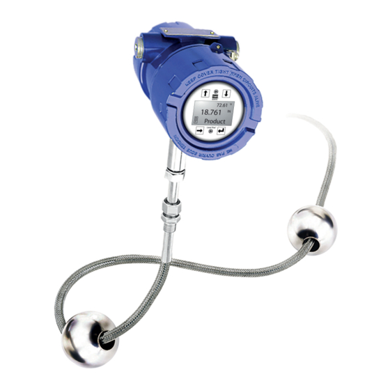
- Page 1 Level Plus ® Magnetostrictive Liquid Level Transmitters with Temposonics Technology ® LevelLimit ® Operation Manual...
-
Page 2: Table Of Contents
Table of contents 1. Contact information ............................3 2. Terms and definitions ............................4 3. Introduction ..............................6 3.1 Purpose and use of this manual ................................6 3.2 Used symbols and warnings ..................................6 4. Safety instructions ............................. 6 4.1 Intended use ......................................6 4.2 Foreseeable misuse .................................... -
Page 3: Contact Information
1. Contact information United States General Tel: +1-919-677-0100 Fax: +1-919-677-2343 E-mail: info.us@mtssensors.com http://www.mtssensors.com Mailing and shipping address MTS Systems Corporation Sensors Division 3001 Sheldon Drive Cary, North Carolina, 27513, USA Customer service Tel: +1-800-633-7609 Fax: +1-800-498-4442 E-mail: info.us@mtssensors.com Technical support and applications... -
Page 4: Terms And Definitions
Level Plus LevelLimit ® ® Operation Manual 2. Terms and definitions Flameproof 6A Heavy Oils Type of protection based on enclosure in which the parts which can ‘Generalized Crude Oils’, Correction of Volume to 60 °F against API ignite an explosive gas atmosphere are placed within and which can Gravity. - Page 5 Level Plus LevelLimit ® ® Operation Manual Strap Table A table of measurement correlating the height of a vessel to the Mass volume that is contained at that height. The transmitter can contain up The property of a body that causes it to have weight in a gravitational to 100 points.
-
Page 6: Introduction
Level Plus LevelLimit ® ® Operation Manual 3. Introduction 4. Safety instructions 3.1 Purpose and use of this manual 4.1 Intended use Important: The liquid level transmitter is intended to be used to measure the level Before starting the operation of the equipment read this of liquid(s) contained by a structure as well as the temperature of documentation thoroughly and follow the safety information. -
Page 7: Foreseeable Misuse
Level Plus LevelLimit ® ® Operation Manual 4.2 Foreseeable misuse 4.3 Installation, commissioning and operation Forseeable misuse Consequence 1. Wear proper personal protection equipment such as hard hat, Wrong sensor connection Possible damage to electronics safety shoes, flame resistant clothing, safety glasses, gloves, and See chapter 7 for Electrical hearing protection. -
Page 8: Product Overview
THE INFORMATION AND DESIGN(S) DISCLOSED 0 PLACES 1 PLACE MTS SYSTEMS CORPORATION ANGLES HEREIN ARE THE PROPERTY OF MTS SYSTEMS SENSORS DIVISION CORPORATION AND MAY NOT BE USED, 3001 SHELDON DRIVE, CARY, NC 27513 REPRODUCED OR DISCLOSED IN ANY FORM •... - Page 9 Level Plus LevelLimit ® ® Operation Manual Outer pipe configurations The outer pipe is constructed of a variety of configurations. The LevelLimit is available in a flexible hose or a rigid pipe. ® Fig. 2: Outer pipe configuration Fig. 3: Outer pipe configuration...
-
Page 10: Accuracy
Level Plus LevelLimit ® ® Operation Manual Floats LevelLimit transmitters offer numerous floats for different ® applications such as stainless steel and Hastelloy for both product ® level and interface level. To be able to accurately detect the interface level there needs to be a difference of at least 0.05 in specific gravities between the product and interface liquids. -
Page 11: Model Number Identification
Level Plus LevelLimit ® ® Operation Manual 5.5 Model number identification a Sensor model g Protection method L LevelLimit Level Transmitter F Explosion proof / Flameproof - PENDING I Intrinsically safe b Sensor pipe X No approval 5/8" OD Rigid Pipe M Flexible, 7/8"OD tube w/bottom fixing eye h Gas group N Flexible, 7/8"OD tube w/bottom fixing weight... -
Page 12: Technical Data
Level Plus LevelLimit ® ® Operation Manual 5.6 Technical data Level Output Measured Variable Product level and interface level Output Signal /Protocol Modbus RTU Flexible hose: 1575...22000 mm (62...866 in.) Order Length Rigid pipe: 305...7620 mm (12...300 in.) Inherent Accuracy ±1 mm (0.039 in.) Repeatability 0.001% F.S. -
Page 13: Technical Drawing
Level Plus LevelLimit ® ® Operation Manual 5.7 Technical drawing 117 mm (4.6 in.) 3/4 in. FNPT 152 mm (6.0 in.) 192 mm Protection (7.6 in.) Method: I or X Protection Method: F 1 in. MNPT with 4 in MNPT adapter 305 mm (12 in.) Manual Switch Test 4 in. - Page 14 Level Plus LevelLimit ® ® Operation Manual 117 mm (4.6 in.) 3/4 in. FNPT 152 mm (6.0 in.) 192 mm Protection (7.6 in.) Method: I or X Protection Method: F 3/4 in MNPT with 4 in MNPT adapter 127 mm (5.0 in.) Manual Switch Test 4 in.
-
Page 15: Installation And Mounting
Level Plus LevelLimit ® ® Operation Manual 6. Installation and mounting 6.4 Installation steps Caution: 6.1 Training When assembling and installing the LevelLimit transmitter, be ® Warning: careful not to allow the flexible hose to kink or be coiled in less When the pipe/hose of the LP-Series level transmitter is installed or than 381 mm (15 in.) diameter. -
Page 16: Mounting
Level Plus LevelLimit ® ® Operation Manual Warning: When the pipe/hose of the LP-Series level transmitter is installed or Flexible hose removed from the tank the release of flammable vapors will occur. Take all necessary precaution when installing or removing the level transmitter due to the release of flammable vapors. -
Page 17: Electrical Connections
Level Plus LevelLimit ® ® Operation Manual 7. Electrical connections 7.1 Basic information A typical intrinsically safe connection for the Level Plus LevelLimit ® ® transmitter includes protective safety barriers, a power supply and a reading or monitoring device. Refer to Agency information in chapter A typical Explosionproof/flame proof connection for the Level Plus ®... -
Page 18: Cable Recommendations
Level Plus LevelLimit ® ® Operation Manual the main difference of having a common junction box for all of the Cable specifications Digital I/O transmitters as shown in Fig. 113. Bus with spurs and tree topologies Cable Type Cat5 or equivalent type cable can also be used together to form a hybrid topology. -
Page 19: Grounding
Level Plus LevelLimit ® ® Operation Manual 7.6 Grounding 7.7 Safety barriers 7.6.1 Safety grounding Refer to Table 4 for entity parameters and Table 5 for example safety barriers Warning: Grounding the transmitter through a threaded conduit connection Entity parameters does not meet the requirements as a grounding of the sensor for Ui = 28 VDC safety. -
Page 20: Commissioning
Level Plus LevelLimit ® ® Operation Manual 8. Commissioning 8.4 Commissioning steps 8.4.1 Modbus 8.1 Training 1. Consult chapter 4.3 before starting. Commissioning should only be conducted by qualified service 2. Remove level transmitter from shipping container. personnel according to IEC 60079-14 or MTS trained service 3. -
Page 21: Inspection
Level Plus LevelLimit ® ® Operation Manual 9.2 Tools 9.4.1 General purpose applications 9.2.1 Tools for Flexbile Hose 9.4.1.1 • 9/16" Socket and ratchet Perform Inspection suggested in chapter 9.3. • Channel Lock pliers • 3/16" Hex Key (Allen wrench) 9.4.1.2 •... -
Page 22: Repair
Level Plus LevelLimit ® ® Operation Manual 10. Repair 10.4 Troubleshooting Symptom Possible cause Action 10.1 RMA policy No power Check voltage at Important: communication transmitter Contact Technical Support or Customer Service for assistance if with transmitter Wiring incorrect Reference installation you suspect that the transmitter is not working correctly. -
Page 23: Setup Software
Level Plus LevelLimit ® ® Operation Manual 12. Interface 10.5 Setup software MTS offers Setup Software that is shipped with the level transmitter 12.1 Modbus output and is also available for download from www.mtssensors.com. The Setup Software is to be used for installation, commissioning, and This Operation and Installation Manual focuses on the mechanical troubleshooting. -
Page 24: Agency Information
Level Plus LevelLimit ® ® Operation Manual 13. Agency information 13.1 Approvals overview The Notified Body is designated in the 8 digit of the model number and the Protection Method is designated in the 9 digit of the model number. These two digits of the model number specify the hazardous area approval that is provided with the selected level transmitter. -
Page 25: Certificates
ETARY DATA TOLERANCES ON AND DESIGN(S) DISCLOSED 0 PLACES 1 PLACE MTS SYSTEMS CORPORATION ANGLES E PROPERTY OF MTS SYSTEMS SENSORS DIVISION AND MAY NOT BE USED, 3001 SHELDON DRIVE, CARY, NC 27513 OR DISCLOSED IN ANY FORM... - Page 26 Level Plus LevelLimit ® ® Operation Manual 13.3.1.3 Installation drawing Fig. 15: Intrinsically Safe FM installation drawing, Modbus, Page 1...
- Page 27 Level Plus LevelLimit ® ® Operation Manual Fig. 16: Intrinsically Safe FM installation drawing, Modbus, Page 2...
- Page 28 Level Plus LevelLimit ® ® Operation Manual 13.3.2 Explosionproof / Flame Proof 13.3.2.1 Specific Conditions of Safe Use 1. Warning: The equipment contains non-metallic enclosure and process parts, to prevent the risk of electrostatic sparking, the non-metallic surface should only be cleaned with a damp cloth. Painted surface of the equipment may store electrostatic charge and become a source of ignition in applications with a low relative humidity <~30% relative humidity where the painted surface is...
-
Page 29: Fmc (Cec)
7.5 POINT SIZE 13.4.1.2 Labels Level Plus Transmitter 47 [.14] 17.53 [.69] APPROVED MTS Systems Corp. Sensors Division 3001 Sheldon Drive, Cary, N.C. 27513 LPXXXXXXXXXXXXXXXXXXXX 35.05 [1.38] XXXXXXXXX XX-XX REFER TO INSTALLATION DWG #651543-2/651594-2 FOR CAUTION/WARNINGS 3.05 [.12] WARNING: SUBSTITUTION OF COMPONENTS MAY IMPAIR INTRINSIC SAFETY Avertissement : Se référer au document DWG # 651543-2/651594-2 précautions d'installations... - Page 30 Level Plus LevelLimit ® ® Operation Manual 13.4.1.3 Installation Drawing Fig. 18: Intrinsically Safe FMC installation drawing, Modbus, Page 1...
- Page 31 Level Plus LevelLimit ® ® Operation Manual Fig. 19: Intrinsically Safe FMC installation drawing, Modbus, Page 3...
- Page 32 Level Plus LevelLimit ® ® Operation Manual 13.4.2 Explosionproof / Flame Proof 13.4.2.1 Specific Conditions of Safe Use 1. Warning: The equipment contains non-metallic enclosure and process parts, to prevent the risk of electrostatic sparking. The non-metallic surface should only be cleaned with a damp cloth. Painted surface of the equipment may store electrostatic charge and become a source of ignition in applications with a low relative humidity <~30 % relative humidity where the painted surface is...
-
Page 33: Atex And Iecex
TOLERANCES ON AND DESIGN(S) DISCLOSED 0 PLACES 1 PLACE MTS SYSTEMS CORPORATION IMENSIONS. ANGLES E PROPERTY OF MTS SYSTEMS SENSORS DIVISION *NO REVISIONS SHALL BE MADE WITHOUT THE NOTIFICATION TO APPROVAL AGENCY(S).*** AND MAY NOT BE USED, ... - Page 34 Level Plus LevelLimit ® ® Operation Manual 13.5.2 Explosionproof / Flame Proof 13.5.2.1 Specific Conditions of Safe Use 1. Warning: The equipment contains non-metallic enclosure and process parts, to prevent the risk of electrostatic sparking. The non-metallic surface should only be cleaned with a damp cloth. Painted surface of the equipment may store electrostatic charge and become a source of ignition in applications with a low relative humidity <~30% relative humidity where the painted surface is...
- Page 35 Level Plus LevelLimit ® ® Operation Manual 13.5.3 EC Declaration of conformity...
- Page 36 MTS, Temposonics and Level Plus are registered trademarks of MTS Systems Corporation in the United States; MTS SENSORS and the MTS SENSORS logo are trademarks of MTS Systems Corporation within the United States. These trademarks may be protected in other countries. All other trademarks are the property of their respective owners. Copyright © 2020 MTS Systems Corporation. No license of any intellectual property rights is granted.
Need help?
Do you have a question about the LevelLimit Level Plus and is the answer not in the manual?
Questions and answers